
Door for a cooking apparatus

Active Publication Date: 2011-11-15
LG ELECTRONICS INC
View PDF130 Cites 8 Cited by
  • Summary
  • Abstract
  • Description
  • Claims
  • Application Information

AI Technical Summary

Problems solved by technology

This type of arrangement also makes it difficult to provide for adequate cooling flow to the heating components and venting of heat and cooking odors from the cooking cavity.

Method used


Image

  • Door for a cooking apparatus
  • Door for a cooking apparatus
  • Door for a cooking apparatus

Examples


Embodiment Construction

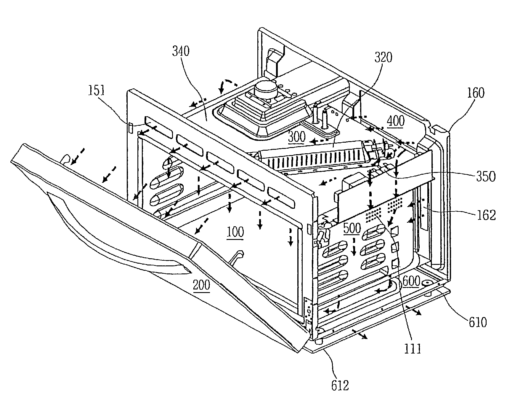
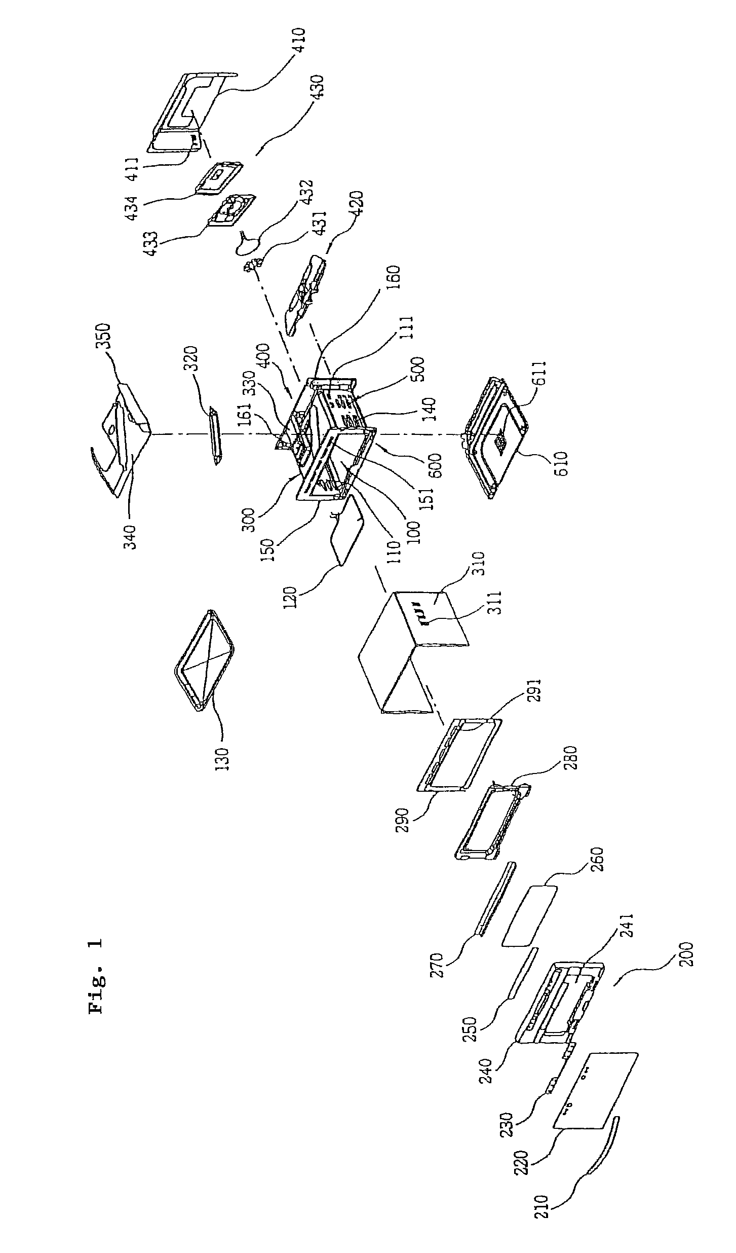
FIG. 1 is an exploded view of an exemplary cooking apparatus as embodied and broadly described herein. The exemplary cooking apparatus may include a cooking cavity 100, a door 200, an upper space 300 located over the cooking cavity 100, a rear space 400 located at the rear of the cooking cavity 100, lateral spaces 500 located on both sides of the cooking cavity 100, and a lower space 600 located under the cooking cavity 100.

The cooking cavity 100 is a space for cooking food, and may be defined by an inner case 110. A heater 120 may be provided at the upper portion and / or lower portion of the inside of the cooking cavity 100, and a plate or a rack 130 may be placed inside the cooking cavity 100. The inner case 110 may include an inlet (not shown) and an outlet 111 formed on the sides for forming an air flow path that directs heat and odors from inside the cooking cavity 100 to an outside of the cooking apparatus. The heater 120 may be, for example, a sheath heater, or other such heat...


PUM


Abstract

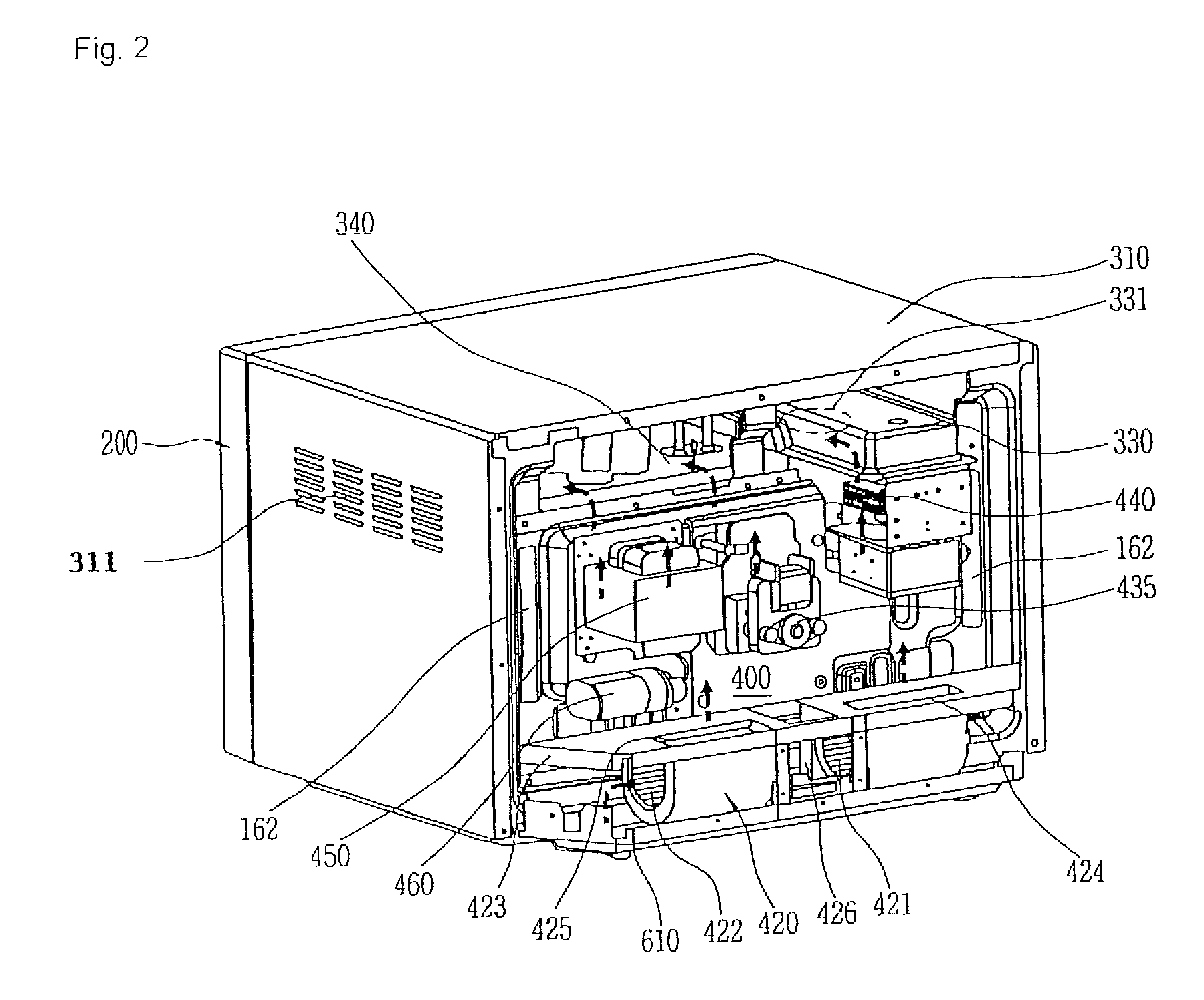
A cooking apparatus is provided. The cooking apparatus includes a cooking cavity, an upper space formed above the cooking cavity, lateral side spaces formed to at opposite lateral sides of the cooking cavity, a rear space formed behind the cooking cavity, and a lower space formed below the cooking cavity. A fan provided in the rear space generates a cooling flow that cools components housed in the rear space. A cooling flow path extends from the rear space and into the upper space and lateral side spaces. Flow from the upper space enters the door to cool the door and is exhausted through a lower portion of the door. Flow from the lateral side spaces, which includes an exhaust flow from the cooking cavity, is guided to the lower space and exhausted. In this manner, the cooking apparatus can be completely cooled and cooking odors and heat appropriately exhausted by the cooling fan positioned in the rear space.

Description

This application claims benefit under 35 U.S.C. §119 from Korean Patent Application Nos. 10-2006-0084335, filed on Sep. 1, 2006; 10-2006-0088289, filed Sep. 12, 2006; 10-2006-0088293, filed Sep. 12, 2006; 10-2006-0088288, filed Sep. 12, 2006; 10-2006-0088294, filed Sep. 12, 2006; 10-2006-0088295, filed Sep. 12, 2006; and 10-2006-0088296, filed Sep. 12, 2006, the entirety of which is incorporated herein by reference.BACKGROUND1. FieldThis relates in general to a heating apparatus, and more specifically, to a cooking apparatus provided with a magnetron and a heater so as to cook food positioned in a cooking cavity thereof.2. BackgroundIn general, a cooking apparatus is an apparatus that cooks food by generating or transferring heat to food placed in a cooking cavity. Examples of such a cooking apparatus may include, for example, a microwave oven, a combined microwave oven and convection oven, a conventionally heated standard oven and the like.A cooking apparatus typically includes a c...

Claims


Application Information

Patent Timeline
IPC IPC(8): H05B6/64
CPCH05B6/6435H05B6/642F24C15/006
Inventor HWANG, KEUN-JAE
Owner LG ELECTRONICS INC
Learn More