Paint roller

a technology of paint rollers and rollers, which is applied in the direction of couplings, portable power tools, carpet cleaners, etc., can solve the problems of difficulty in maintaining a distance between the handle and the handle, difficulty in applying paint to the high horizontal joint, and awkward and uncomfortable positions

Inactive Publication Date: 2011-11-22
WILLIAMS MAKOLLE
View PDF15 Cites 17 Cited by
  • Summary
  • Abstract
  • Description
  • Claims
  • Application Information

AI Technical Summary

Benefits of technology

[0009]In at least one embodiment the inventive paint roller reduces the working forces by 60 to 70%. This may be done by articulating the bearing dynamics of the roller head instead of a shoulder joint and / or rotation of the user's arm and wrist. In some applications of the inventive paint roller the user can paint just by walking horizontally in the presence of any surface while guiding the paint roller as it rest on the work surface.
[0010]The inventive paint roller universally articulates and compliments anyone using this type of tool because it substantially reduces up to 70% of the body mechanics that cause carpal tunnel, rotator cuff injuries as well as neck and lower back strains. In some embodiments the user can apply a coating on any surface without using a vertical arm lifting of the roller once it is loaded with paint and placed on a vertical or horizontal surface. In some applications the user does not have to raise his elbow to shoulder height even when painting an overhead surface.
[0011]In some applications of the inventive paint roller the user can paint at heights up to twenty feet and “cut in” accurately “the grid” even on a round column, thereby eliminating the inefficient surface strokes that only apply a coating of paint using 25% of the roller surface when using the standard paint roller. Rather, this articulating paint roller using its dynamics would place 100% of the roller on the standing column and apply any coating 360 degrees around the column without the repetitive inefficient vertical stroke employed on such a surface as is common today. The painter simply could position in front of the column, set the roller head in a vertical configuration, and roll the applicator horizontally from the top of column to bottom. If desired the roller could be inverted to complete painting the lower portion of the column. This allows the user of this unique paint roller to avoid having to back away from the painting surface to accomplish long strokes. Such a feature can also allow a user to paint in very tight places.

Problems solved by technology

For example, the U-shaped configuration of the shaft renders it difficult to apply paint to a high horizontal joint, such as the joint between a wall and the ceiling in a room.
However, because the U-shaped shaft orientates the tubular paint applicator perpendicular to the handle, the user's forearm must be positioned in-line with the rolling direction of the applicator, thereby requiring the user to be elevated and paint from an awkward and uncomfortable position when painting an elevated horizontal joint.
Other drawbacks associated with the U-shaped handle occur when an elongated handle is employed to allow painting of elevated surfaces without use of a ladder or scaffolding.
One such drawback is the difficulty in maintaining a distance between the handle and the vertical surface to be painted, which is sufficient to prevent the handle from contacting the surface and marking the surface.
This problem is of particular concern as the length of the elongated handle increases because of the arch created in the elongated handle from the forward force applied in order to maintain the applicator in contact with the surface.

Method used


Image

  • Paint roller
  • Paint roller
  • Paint roller

Examples


first embodiment

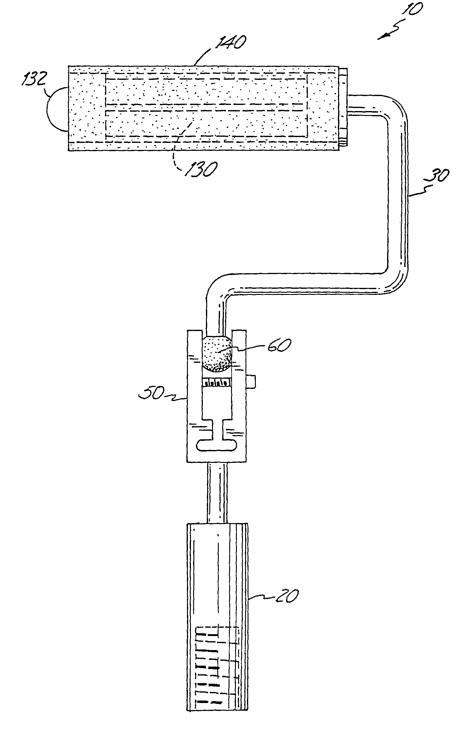
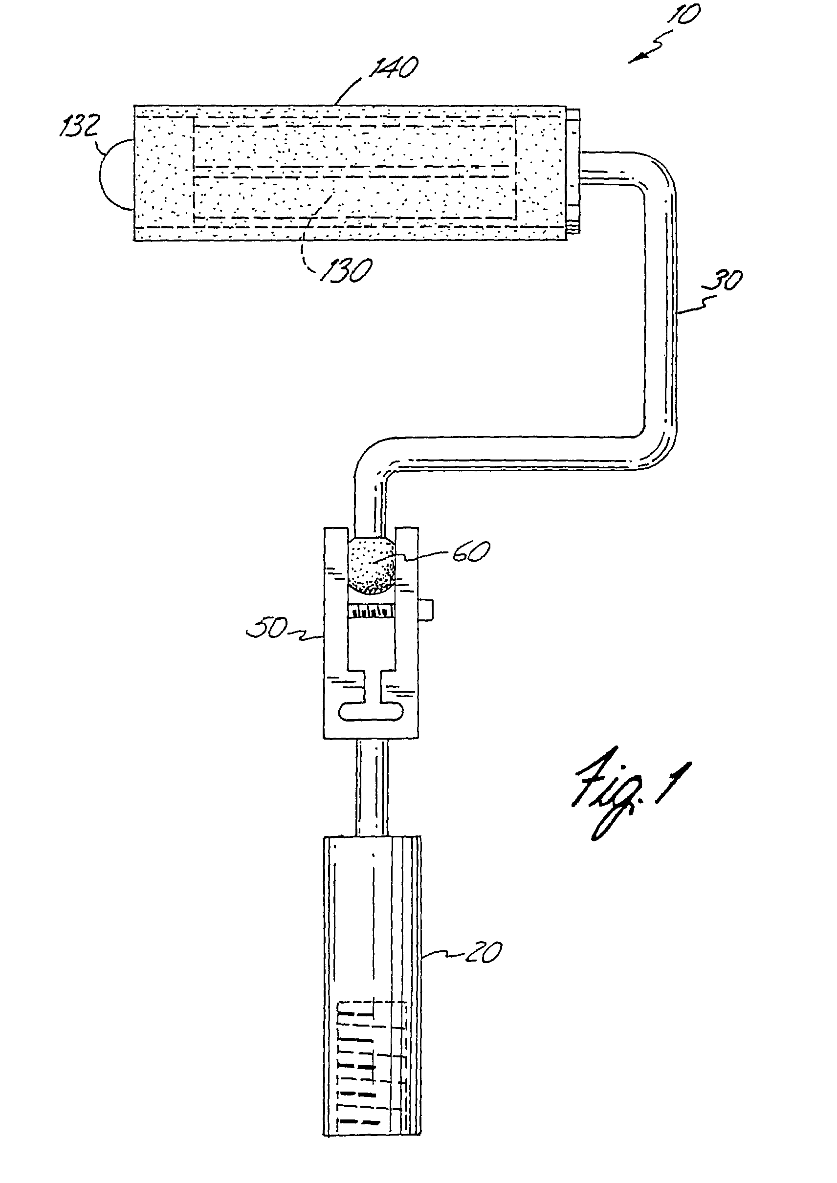
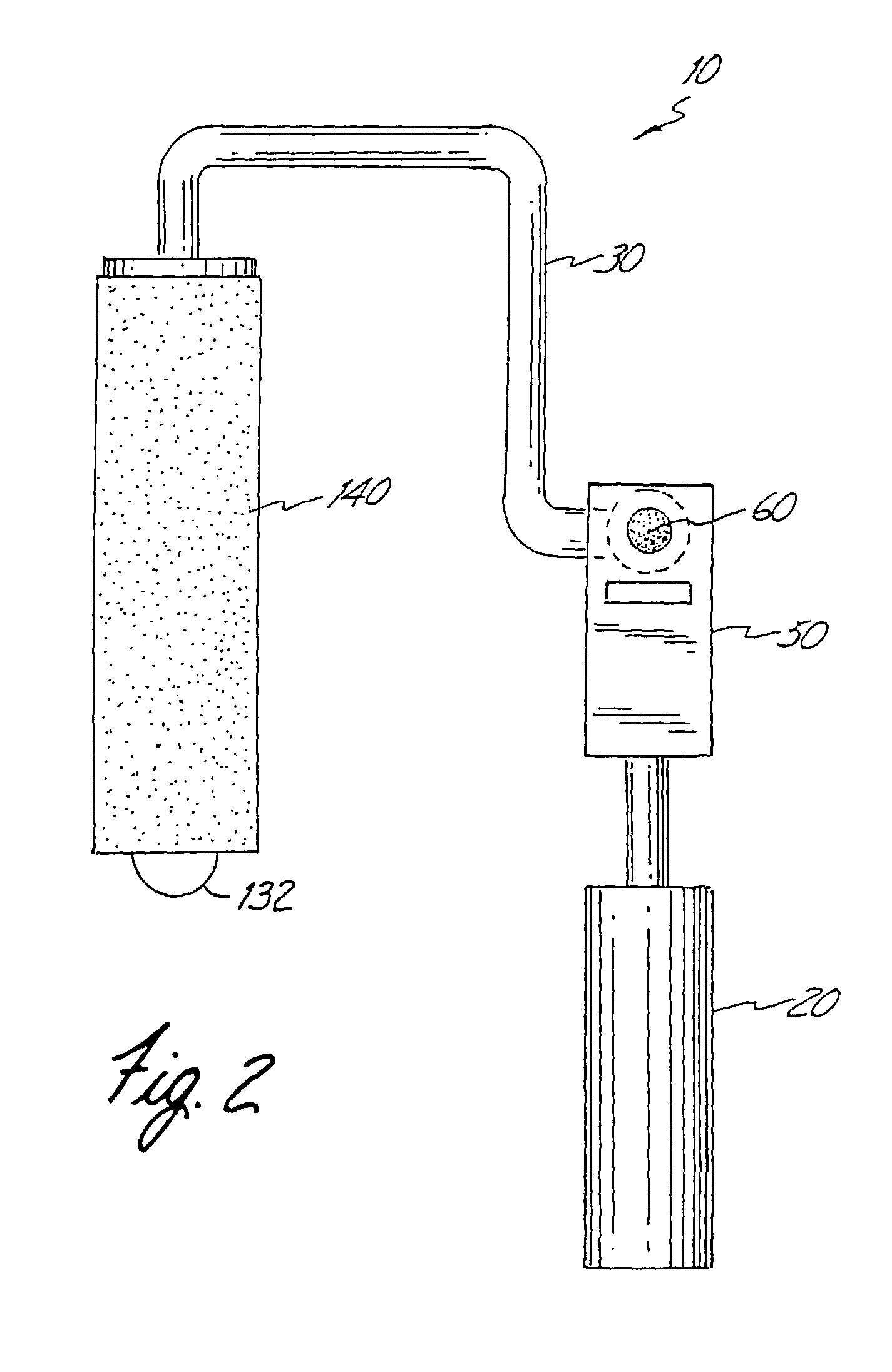
[0103]One embodiment of the paint roller 10 is shown in FIGS. 1-4. The paint roller 10 includes a handle 20, a shaft 30, a flexure joint 50, a connector 100, and a tube-receiving frame 130. The tube-receiving frame 130 is configured and arranged to accept a tubular paint applicator 140. The second end 22 of the handle 20 is selectively secured to the first end section 31 of the shaft 30 by the flexure joint 50. The tube-receiving frame 130 is rotatably secured to the second end 32 of the shaft 30.

[0104]The handle 20 preferably includes a grip portion 23 and a neck portion 24. The grip portion 23 may be constructed from any number of materials possessing the necessary structural integrity including specifically but not exclusively, aluminum, ceramic, wood and molded plastic. The grip portion 23 is preferably sized to comfortably rest within a user's hand (not shown). In this regard, the grip portion 23 may include finger articulations for enhancing fit with a user's hand. The neck po...

second embodiment

[0130]A second embodiment of the paint roller 10 is shown in FIGS. 5 through 17. The second embodiment of the paint roller 10 is similar in many respects to the first embodiment of the paint roller 10. Accordingly, similar components and features will be identified by the same reference numeral.

[0131]Referring to FIG. 5, the paint roller 10 includes a handle 20, a shaft 30, a locking mechanism 40, a flexure joint 50, a connector 100, a spacing adjustment mechanism 120, and a tube-receiving frame 130. The tube-receiving frame 130 is configured and arranged to accept a tubular paint applicator 140. The second end 22 of the handle 20 is selectively secured to the first end section 31 of the shaft 30 by the flexure joint 50. The tube-receiving frame 130 is rotatably secured to the second end 32 of the shaft 30.

[0132]The handle 20 preferably includes a grip portion 23 and a neck portion 24. The grip portion 23 may be constructed from any number of materials possessing the necessary struc...


PUM


Abstract

A paint roller including a shaft, a handle attached to a first end of the shaft, and at least one of (a) a frame with an axial protrusion, and (b) a flexure joint with one or more functional elements. The frame is configured and arranged to be rotatably secured to a second end of the shaft for operably engaging a paint roller head and rotating the paint roller head about an axis. The protrusion extends in a second axial direction from the distal end of the frame so as to prevent a distal end of a paint roller head operably engaged upon the frame from contacting a surface perpendicular to the axis of rotation. The flexure joint is configured and arranged to be interposed between and connect the second end of the handle and the first end of the shaft. The functional element is configured and arranged to be secured to a second end of the shaft. The flexure joint includes a receiving member with first and second transversely spaced opposing arms defining a transverse gap between the arms, a spherical member positioned within the gap, a connector in communication with the arms for adjusting the transverse width of the gap occupied by the spherical member and a spacing adjustment mechanism also in communication with the arms for adjusting the transverse width of the gap occupied by the spherical member.

Description

CROSS REFERENCE TO RELATED APPLICATIONS[0001]This application is a continuation-in-part of U.S. application Ser. No. 11 / 140,692 filed May 31, 2005 (now abandoned), which is a continuation-in-part of U.S. application Ser. No. 09 / 919,534 filed Jul. 31, 2001 (now abandoned), which is a continuation-in-part of U.S. application Ser. No. 09 / 490,417 filed Jan. 24, 2000 (now abandoned).FIELD OF THE INVENTION[0002]The invention relates to paint rollers.BACKGROUND OF THE INVENTION[0003]Hand-held paint rollers are commonly employed to apply paint to large flat surfaces such as the interior walls of a room and the exterior siding of a residence. Standard paint rollers include a handle, a U-shaped shaft connected to a longitudinal end of the handle, and a tube-receiving frame rotatably connected to the free end of the shaft. The tube-receiving frame is sized to selectively receive and maintain a tubular paint applicator.[0004]By employing a U-shaped shaft, the standard paint roller centrally pos...

Claims


Application Information

Patent Timeline
Patent Type & Authority Patents(United States)
IPC IPC(8): B05C17/02B25G1/06B25G3/38
CPCB05C17/022B05C17/0222Y10T403/32311
Inventor WILLIAMS, MAKOLLE
Owner WILLIAMS MAKOLLE
Why Eureka
Try Eureka