
Method and apparatus for detecting wear of tire

a tire wear and tire technology, applied in vehicle tyre testing, instruments, roads, etc., can solve the problems of significant changes in tire performance and greater risks of tire burst, and achieve the effects of greater accuracy, excellent efficiency and great accuracy

Active Publication Date: 2011-11-22
BRIDGESTONE CORP
View PDF14 Cites 41 Cited by
  • Summary
  • Abstract
  • Description
  • Claims
  • Application Information

AI Technical Summary

Benefits of technology

The invention aims to solve the problem of detecting the state of wear of the tire tread with high accuracy while ensuring durability. The current method requires embedding a tire-mounted unit in the tire tread, which is troublesome to fabricate and may compromise the durability of the sensor. The present invention provides a solution to this problem.

Problems solved by technology

Generally tire wear causes significant changes in tire performance, a drop in draining performance on wet road surfaces being among them, depending of the degree of wear.
If tire wear further advances, there will be greater risks of tire burst.

Method used


Image

  • Method and apparatus for detecting wear of tire
  • Method and apparatus for detecting wear of tire
  • Method and apparatus for detecting wear of tire

Examples


Embodiment Construction

[0047]Preferred embodiments of the present invention will be described hereinbelow with reference to the accompanying drawings.

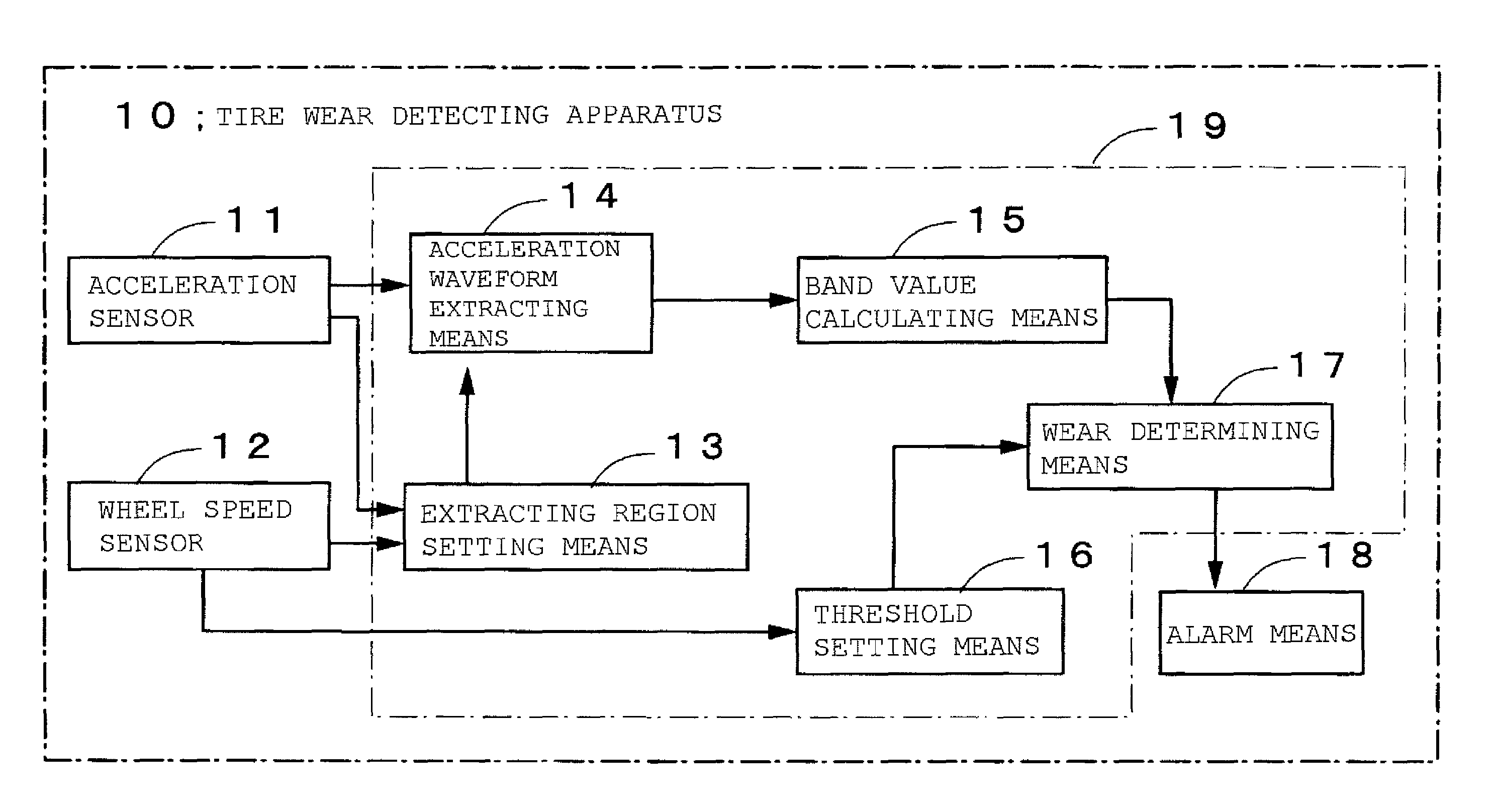
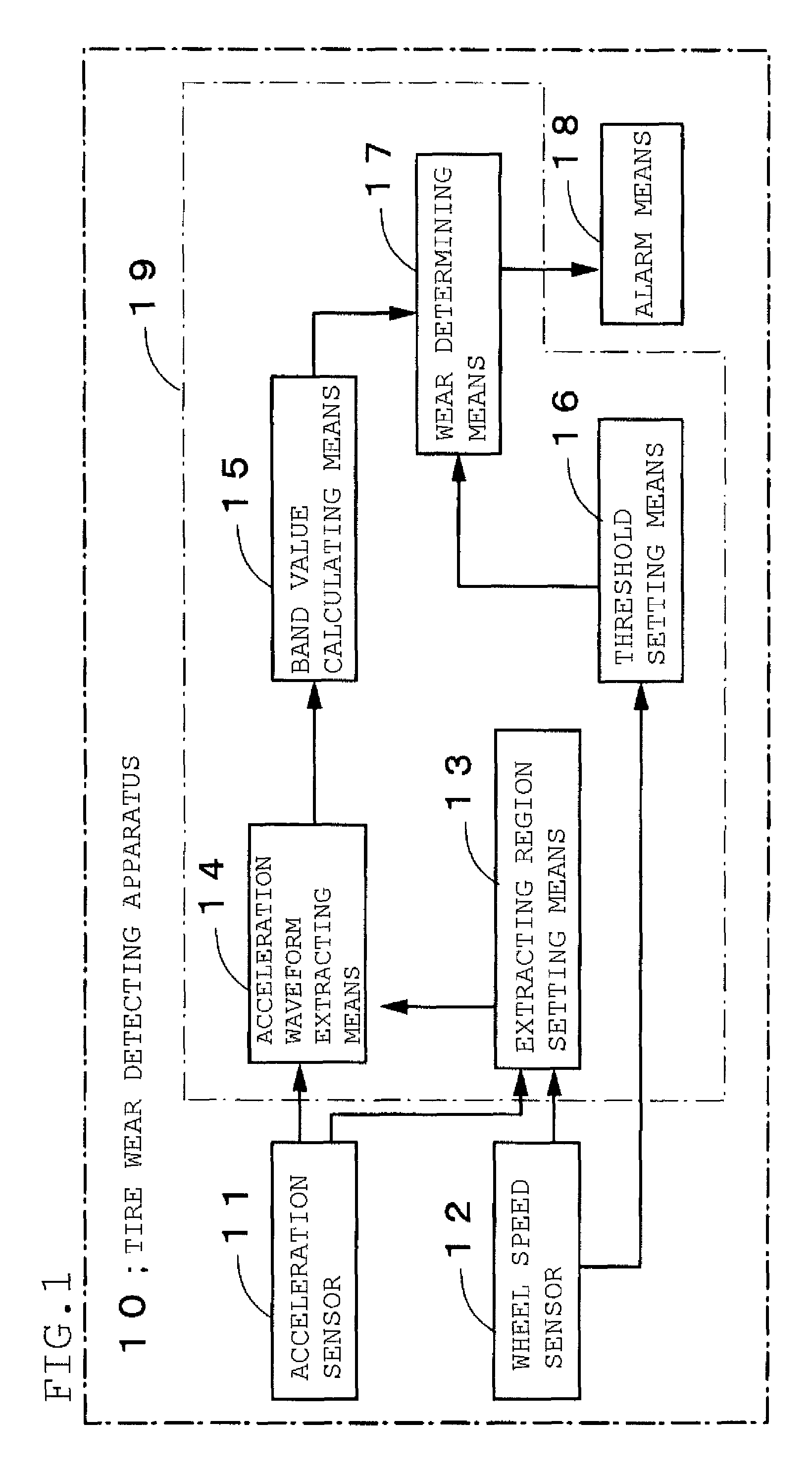
[0048]FIG. 1 is a functional block diagram showing a structure of a tire wear detecting apparatus 10 according to a preferred embodiment of the present invention. In the figure, reference numeral 11 denotes an acceleration sensor for detecting an acceleration of the inner surface of the tire tread, 12 a wheel speed sensor for detecting the rotational speed of a wheel, 13 an extracting region setting means for calculating a time interval between peak positions by detecting the peak position appearing near the leading block point and the peak position appearing near the trailing block point of the acceleration waveform detected by the acceleration sensor and determining the length of the leading edge region of the acceleration waveform based on the wheel speed detected by the wheel speed sensor 12 and the time interval, 14 an acceleration waveform extracting m...


PUM


Abstract

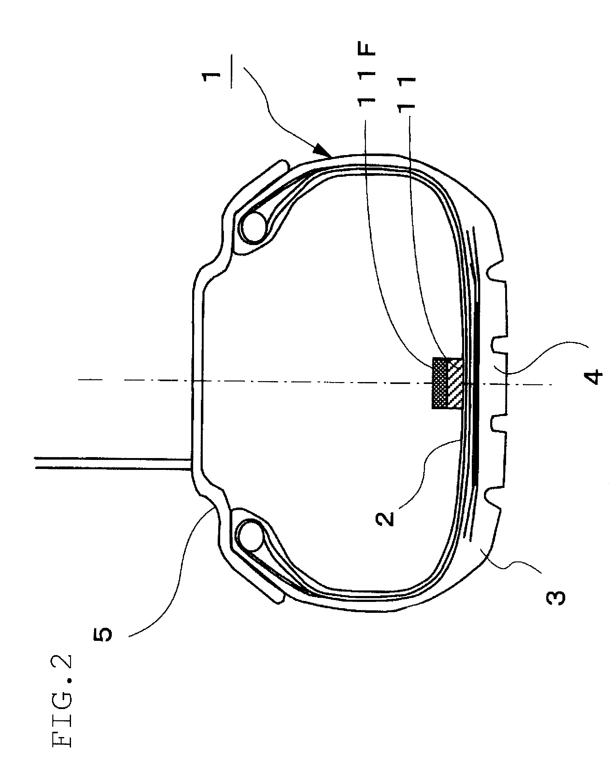
A method and apparatus for detecting the state of wear of the tire tread with accuracy and durability are provided. Acceleration of the inner surface of the tire tread is detected by an acceleration sensor installed in an inner liner region of the tire. From a thus detected time-series waveform of acceleration, an acceleration waveform in the leading edge region including a leading peak which occurs when the block engages with the road surface or an acceleration waveform in the trailing edge region including a trailing peak which occurs when the block disengages from the road surface is extracted. A frequency band value Pf is calculated which is the magnitude of acceleration in a predetermined frequency region of a frequency spectrum obtained through a frequency analysis of the extracted acceleration waveform. And the degree of tire wear is determined by comparing the frequency band value Pf with a preset threshold K(v).

Description

CROSS REFERENCE TO RELATED APPLICATIONS[0001]This is a National Stage of International Application No. PCT / JP2008 / 062048 filed Jul. 3, 2008, claiming priority based on Japanese Patent Application No. 2007-181776, filed Jul. 11, 2007, the contents of all of which are incorporated herein by reference in their entirety.TECHNICAL FIELD[0002]The present invention relates to a method for detecting the progress of tire wear and an apparatus therefor.BACKGROUND ART[0003]Generally tire wear causes significant changes in tire performance, a drop in draining performance on wet road surfaces being among them, depending of the degree of wear. Therefore, it is important to detect the condition of tires coming in contact with the road surface, especially, the degree of wear, if the safety of vehicular operation is to be enhanced. If tire wear further advances, there will be greater risks of tire burst.[0004]A method for estimating the amount of tire wear, as shown in FIGS. 8A to 8C, proposes the u...

Claims


Application Information

Patent Timeline
Patent Type & Authority Patents(United States)
IPC IPC(8): G01M17/02B60C11/24
CPCB60C11/24G01M17/02B60C11/246B60C11/243
Inventor HANATSUKA, YASUSHI
Owner BRIDGESTONE CORP
Learn More