CATV port terminator with contact-enhancing ground insert

a technology of catv port terminator and ground insert, which is applied in the direction of coupling device connection, coupling device base/case, two-part coupling device, etc., can solve the problems of poor signal quality, loose connectors, and affecting service quality of catv systems

Active Publication Date: 2011-11-22
PPC BROADBAND INC
View PDF51 Cites 106 Cited by
  • Summary
  • Abstract
  • Description
  • Claims
  • Application Information

AI Technical Summary

Benefits of technology

[0007]Briefly stated, a port terminator includes an outer nut, which may be either electrically conductive or non-electrically conductive, and an electrically conductive ground insert. A portion of the ground insert captures a ground portion of a termination resistor, while a deformable portion of the ground insert makes electrical contact with a connection end of an equipment port when the port terminator is screwed onto the equipment port. The deformable portion can take the form of a flexible brim or a plurality of petals. The petals preferably alternate between flat petals and biased petals. The ground insert permits the port terminator to make a uniform RF seal on an equipment port even with a range of tightening torques.
[0009]According to an embodiment of the invention, a method for manufacturing a port terminator for use in a coaxial cable system includes the steps of forming an outer nut having first and second chambers; forming at least one thread on an inside of the first chamber; forming an electrically conductive ground insert, wherein the ground insert includes a capture portion, a middle portion, and a deformable portion, with the capture portion connected to the middle portion, and the middle portion connected to the deformable portion via a transition band; positioning the ground insert inside the second chamber; providing a termination resistor including a ground portion, an insulator portion, and a conductor portion, wherein an electrical resistance is electrically connected between the conductor portion and the ground portion and surrounded by the insulator portion; positioning the ground portion of the termination resistor inside the capture portion of the ground insert; and fastening the ground portion of the termination resistor to the capture portion of the ground insert, thereby making good electrical contact between the termination resistor and the ground insert.

Problems solved by technology

CATV systems continue to be plagued with service quality problems resulting from loose connections.
For the most part, these connectors are loose because they were not installed to the proper torque, which can occur for a number of reasons from laziness, a lacking of training, and improper use of / inadequate tools.
An improperly installed connector will result in poor signals, because there are gaps between the devices, resulting in a leak of radio frequency (“RF”) signal.
If these two surfaces are not tightly connected, a gap will exist creating a loss in RF signal, resulting in lower quality cable signal.
The spring biases the connector face towards a port after the nut is rotated around the connector a certain number of times. While this device is effective, it requires time and cost in the manufacturing process of the connector.
As a result, it is not unusual for there to be unused ports, particularly in systems with low penetration.
When unused ports are left unterminated, or are terminated with port connectors which are easily left loose by the installer, or which become loose with the vibrations common to an urban environment, significant degradation to CATV service occurs.

Method used


Image

  • CATV port terminator with contact-enhancing ground insert
  • CATV port terminator with contact-enhancing ground insert
  • CATV port terminator with contact-enhancing ground insert

Examples


first embodiment

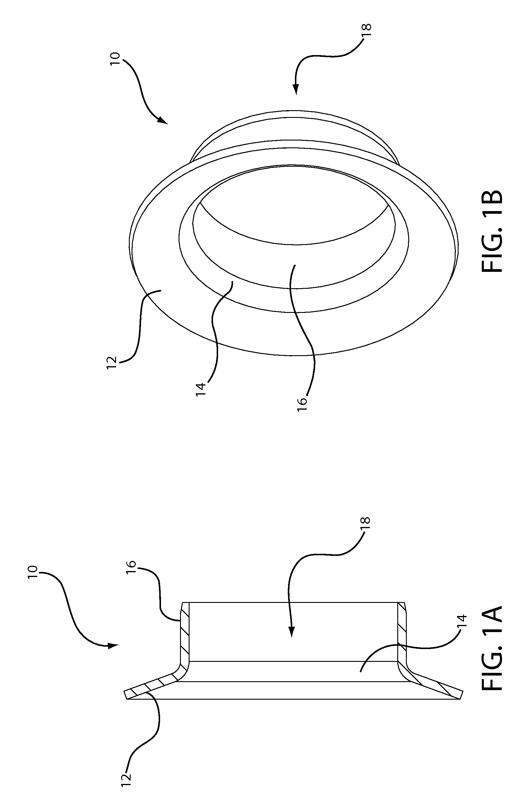
[0027]The last region of the flexible RF seal is the tubular insert portion 16. The tubular insert portion 16 is below the transition band 14. The tubular insert portion 16 is cylindrical in shape and depending on its embodiment can be used to sit on the inside or outside of a post within a coaxial cable connector. Defined within the tubular insert portion 16 is an insert chamber 18. The tubular insert portion 16, in the flexible RF seal 10, sits within a post member of a cable connector (as shown in FIG. 3). As a result, the insert chamber 18 assists in housing a coaxial cable on which the cable connector is placed.

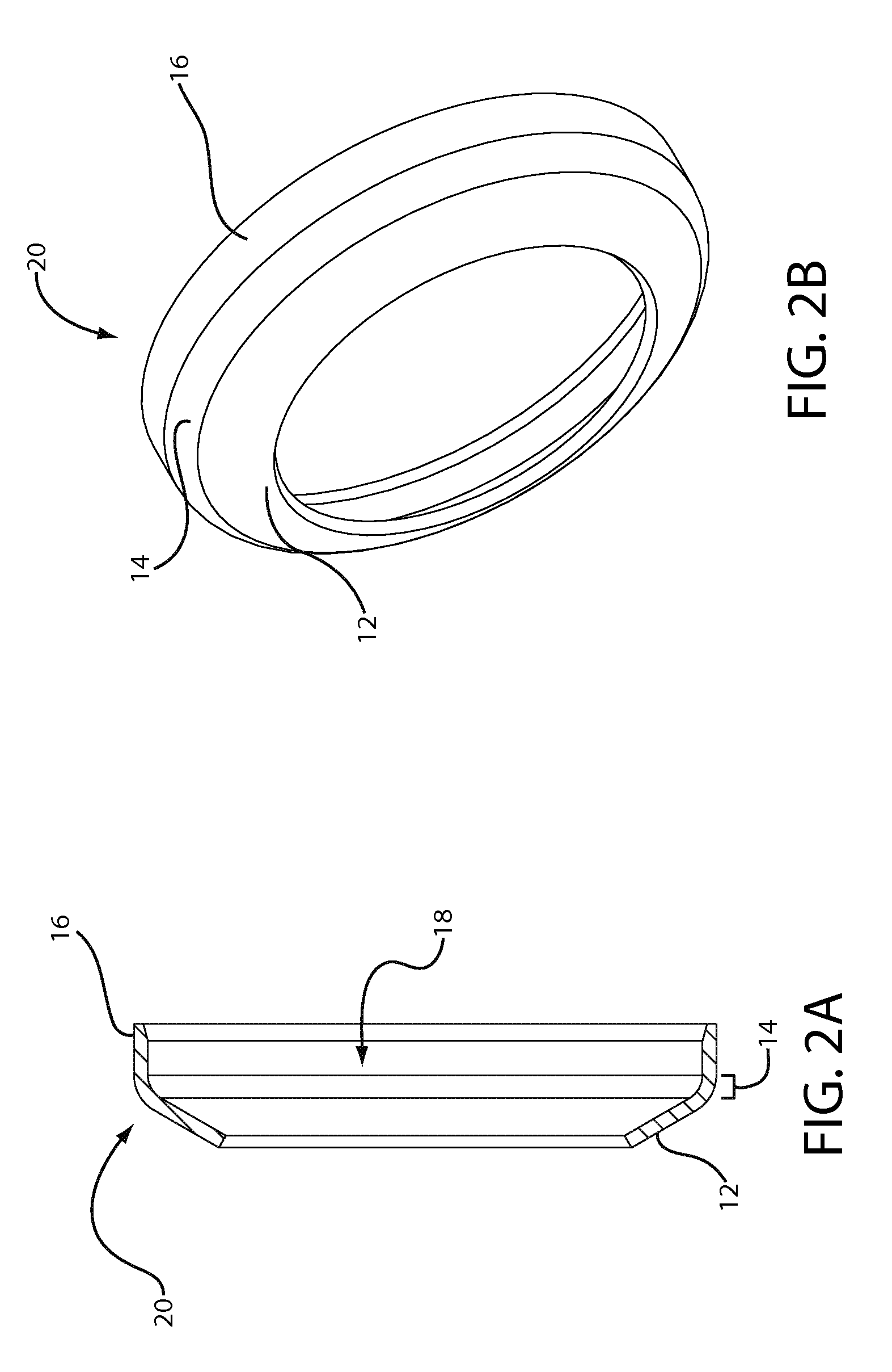
[0028]Referring to FIGS. 2A and 2B, there is a second embodiment of the flexible RF seal, denoted by a reference numeral 20. The flexible RF seal 20 has the same three regions as the first embodiment: a flexible brim 12, a transition band 14, and a tubular insert 16. Further, defined within the flexible RF seal 20, as with the first embodiment 10, is an insert chamber 18...

second embodiment

[0033]Referring to FIG. 4, the seal 20 is shown coupled to connector 100. The seal 20 sits on the outside of the flange end 44 of the post 40. In this position, an end of tubular insert portion 16 abuts the seal 20 and the nut flange 34, with a remainder of tubular insert portion 16 sandwiched between the flange end 44 of the post 40 and a portion of nut 30. The flexible brim 12 extends past the flange end 44, but is not flush with the flange end 44 so that it can adapt to the shape of both the cable port and the connector 100 with the coaxial cable housed within it. In this embodiment, the post 40 does not require a lip 42, as was shown in FIG. 3 with the seal 10. Once the connector 100 engages the cable port and is advanced to have an inner conductor of the cable enter the port, the seal 20 can be deformed to a position necessary to fill gaps or tightly connect, physically and electrically, the connector 100 to the port.

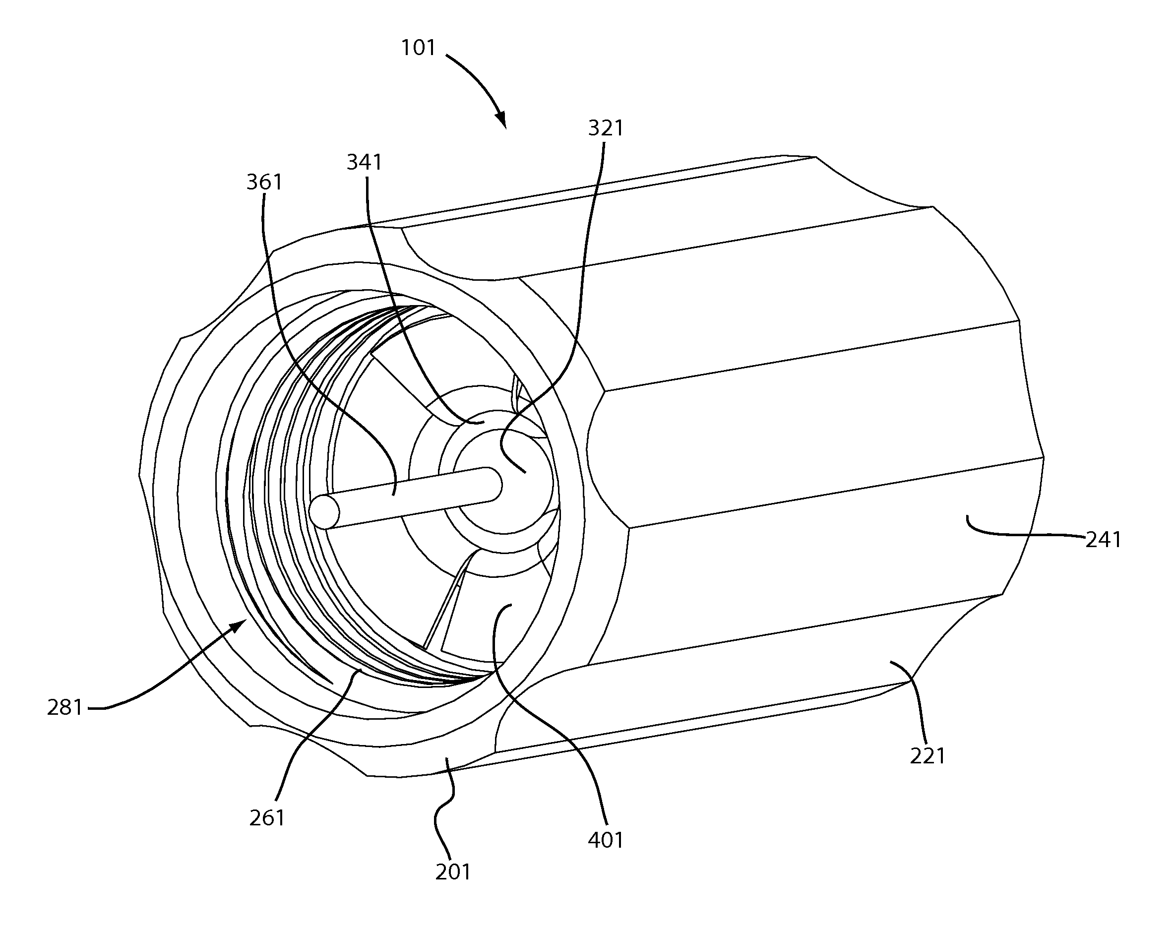
[0034]Referring to FIG. 5, a port terminator 101 is shown. As...


PUM


Abstract

A port terminator includes an outer nut, which may be either electrically conductive or non-electrically conductive, and an electrically conductive ground insert. A portion of the ground insert captures a ground portion of a termination resistor, while a deformable portion of the ground insert makes electrical contact with a connection end of an equipment port when the port terminator is screwed onto the equipment port. The deformable portion can take the form of a flexible brim or a plurality of petals. The petals preferably alternate between flat petals and biased petals. The ground insert permits the port terminator to make a uniform RF seal on an equipment port even with a range of tightening torques.

Description

CROSS-REFERENCE TO RELATED APPLICATIONS[0001]This application is a continuation-in-part of and claims priority from U.S. patent application Ser. No. 12 / 140,573 filed on Jun. 17, 2008, now U.S. Pat. No. 7,753,705 and entitled FLEXIBLE RF SEAL FOR COAXIAL CABLE CONNECTOR, which is a continuation of and claims priority from U.S. application Ser. No. 11 / 553,115 filed Oct. 26, 2006 and entitled FLEXIBLE RF SEAL FOR COAXIAL CABLE CONNECTOR, now, abandoned, both of which are incorporated herein by reference.FIELD OF THE INVENTION[0002]This invention relates generally to the field of CATV port terminators, and more particularly to a port terminator which incorporates a contact-enhancing ground insert for a termination resistor.BACKGROUND OF THE INVENTION[0003]CATV systems continue to be plagued with service quality problems resulting from loose connections. For the most part, these connectors are loose because they were not installed to the proper torque, which can occur for a number of rea...

Claims


Application Information

Patent Timeline
Patent Type & Authority Patents(United States)
IPC IPC(8): H01R13/52
CPCH01P1/266H01R13/6616H01R24/40H01R4/48
Inventor MONTENA, NOAHHAUBE, RICHARD
Owner PPC BROADBAND INC
Why Eureka
Try Eureka