Balance board

a balance board and balance technology, applied in the field of balance boards, can solve the problems of significant manufacturing problems, inability to practice the sport concerned, and limitations in the exercise which the user can perform, and achieve the effect of reducing the likelihood of the user falling off the balance board

Active Publication Date: 2011-11-22
SMITH NICHOLAS DAVID
View PDF15 Cites 20 Cited by
  • Summary
  • Abstract
  • Description
  • Claims
  • Application Information

AI Technical Summary

Benefits of technology

[0005]The present disclosure seeks to overcome these drawbacks in prior arrangements and, in particular, to do so by providing constructions that are relatively straightforward, and therefore relatively inexpensive, to manufacture.
[0006]Accordingly, in one aspect of this disclosure, there is provided a balance board having a top side and an under side, the under side being arranged to be mounted on top of a ball with a user balancing on the top side, the board being shaped to define a generally longitudinal direction and a direction generally transverse to the longitudinal direction, the board being formed from a first top portion defining said topside and having a substantially flat region on its under side and a second lower portion joined to the first top portion and defining a wall at least substantially bounding a portion of said flat region, the distance across said portion in the longitudinal direction of the board being greater than in the transverse direction, so that, with the said portion balanced on a ball with a diameter less than the distance across the said portion in the transverse direction, the board is enabled to move relative to the ball with at least a degree of spherical rotational freedom and also a degree of translational freedom in directions other than the vertical.
[0007]According to a second and alternative aspect of the present disclosure, there is provided a balance board having a top side and an under side, the under side being arranged to be mounted on top of a ball with a user balancing on the top side, the board being shaped to define a generally longitudinal direction and a direction generally transverse to the longitudinal direction, the board being formed from a first top portion defining said topside and a second lower portion substantially co-extensive with the top portion in the longitudinal and transverse directions and being joined to the first top portion, the second portion having a through opening therein, whereby a substantially flat portion of the underside of the first portion is exposed, said portion being bounded by a wall defined by said through opening, the distance across said portion in the longitudinal direction of the board being greater than in the transverse direction, so that, with the said portion balanced on a ball with a diameter less than the distance across the said portion in the transverse direction, the board is enabled to move relative to the ball with at least a degree of spherical rotational freedom and also a degree of translational freedom in directions other than the vertical.

Problems solved by technology

Surfers, snowboarders and skateboarders want to be able to practice skills, notably balance, relevant to their particular sports at times when, for one reason or another (such as lack of snow or of surfable waves), it is not possible to practice the sport concerned.
The mounting of such spheres or rollers beneath a board presents significant manufacturing problems.
Moreover, all these arrangements suffer from limitations in the exercises which the user can perform.
The user may frequently fall, for example by the ball rolling away from under the board.
However, this results in a board with a complex construction, that is too expensive to sell on a commercial scale at a price which ordinary surfers, snowboarders and skateboarders can afford.
These arrangements also failed satisfactorily to restrain movement of the ball beyond the cavity, as a smoothly concave shape right up to the lip simply guided the ball towards the lip, and a simple excess movement tended to carry the ball over the lip, causing the user to fall.
Other attempts to restrict movement of the ball either restrict the range of different movements possible or still result in a board from which a user can easily fall in use.

Method used


Image

  • Balance board
  • Balance board
  • Balance board

Examples


Embodiment Construction

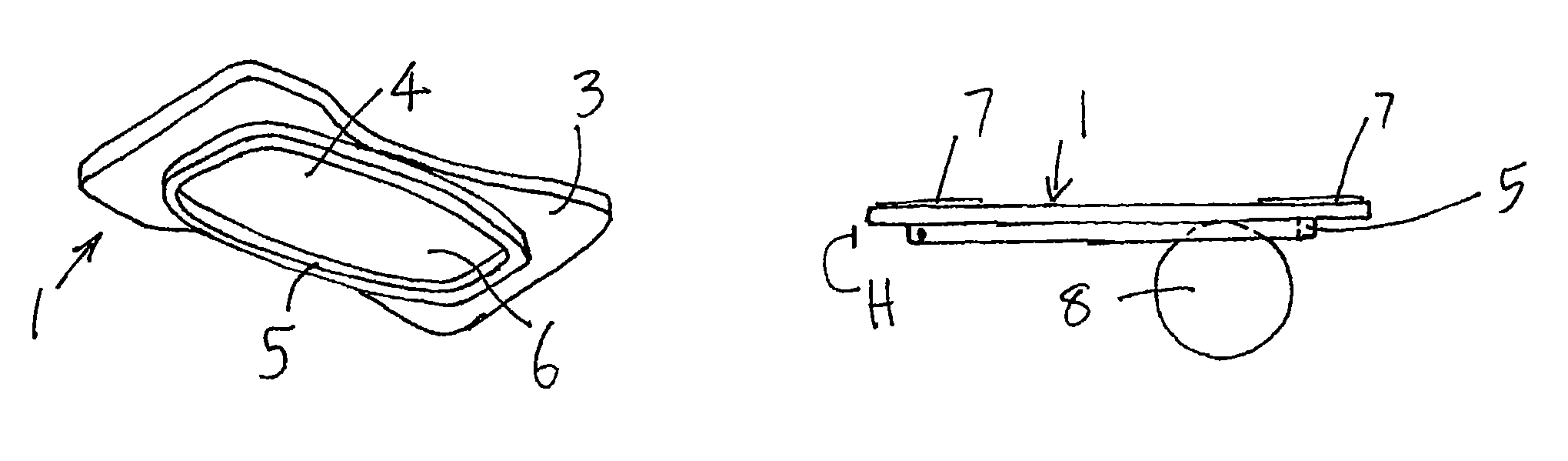
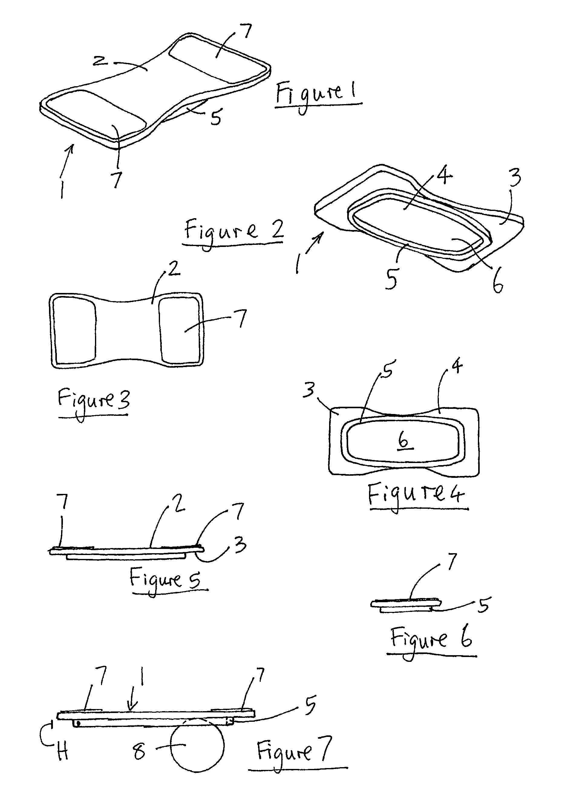
[0035]Referring first to FIGS. 1 to 7, a balance board 1 has a top side 2 and an under side 3. The under side 3 includes a substantially flat region 4 to which is mounted an endless wall member 5 which, as explained in more detail below, is preferably made in several sections which are joined or abutted.

[0036]The endless wall 5 depends from the under side 3 and defines a portion 6 of the flat region 4 within and bounded by the wall 5. As can be seen, in particular from FIGS. 2, 4 and 5, the bounded portion 6 makes up the greater part of the under side of the board.

[0037]Top side 2 of the board is provided with spaced contact surfaces 7 at opposite longitudinal ends of the top side 2. Contact surface portions 7 are adapted to prevent a user's feet from slipping when using the board. In a preferred arrangement, a grip tape, for example the tape available from Heskins Ltd of Chorley, Lancashire, PR6 8RQ under the Trademark Safety-Grip™ or the tape available from TBS Eram-Industrie of C...


PUM


Abstract

A balance board has a top side and an under side. The under side is arranged to be mounted on top of a ball with a user balancing on the top side. The board is shaped to define a generally longitudinal direction and a direction generally transverse to the longitudinal direction. The board is formed from a first top portion defining the topside and having a substantially flat region on its under side and a second lower portion joined to the first top portion and defining a wall at least substantially bounding a portion of the flat region. The distance across the bounded portion in the longitudinal direction of the board is greater than in the transverse direction. With the bounded portion balanced on a ball with a diameter less than the distance across the bounded portion in the transverse direction, the board is enabled to move relative to the ball with at least a degree of spherical rotational freedom and also a degree of translational freedom in directions other than the vertical.

Description

CROSS REFERENCE TO RELATED APPLICATIONS[0001]This application claims priority under 35 U.S.C. §119 based on GB Application No. 0612018.2 filed Jun. 16, 2006, GB Application No. 0704032.2 filed Mar. 2, 2007 and WO PCT / GB2007 / 002245 filed Jun. 15, 2007.BACKGROUND[0002]This disclosure relates to balance boards.[0003]Surfers, snowboarders and skateboarders want to be able to practice skills, notably balance, relevant to their particular sports at times when, for one reason or another (such as lack of snow or of surfable waves), it is not possible to practice the sport concerned. In an effort to meet this demand a number of devices, known generally as balance boards, have been suggested in the literature, and some of these are also commercially available. Such boards also have a use in Physiotherapy and in rehabilitation of accident victims. Balance boards also have value as sports and exercise items in their own right.[0004]In general such devices comprise a board on which a user may st...

Claims


Application Information

Patent Timeline
Patent Type & Authority Patents(United States)
IPC IPC(8): A63B21/00
CPCA63B21/0004A63B22/16A63B69/0093A63B22/18A61H1/003A63B2022/0033A63B26/003
Inventor SMITH, NICHOLAS DAVID
Owner SMITH NICHOLAS DAVID
Why Eureka
Try Eureka