Power supply system and method for the operation of an electrical load

Active Publication Date: 2011-11-22
DIALOG SEMICON UK
View PDF38 Cites 1 Cited by
  • Summary
  • Abstract
  • Description
  • Claims
  • Application Information

AI Technical Summary

Benefits of technology

[0005]It is an object of the present invention to specify a current source arrangement and a method for operat

Problems solved by technology

If an excessively low voltage is dropped across t

Method used


Image

  • Power supply system and method for the operation of an electrical load
  • Power supply system and method for the operation of an electrical load
  • Power supply system and method for the operation of an electrical load

Examples


Example

DETAILED DESCRIPTION OF THE DRAWINGS

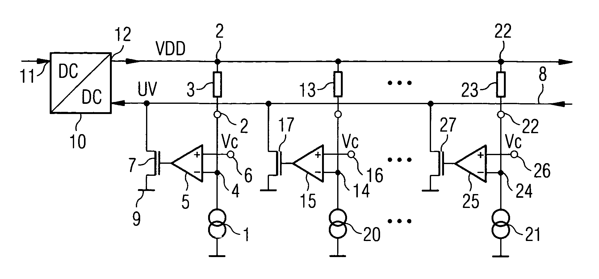
[0033]FIG. 1 shows a current source arrangement according to an embodiment of the invention. A current source 1 is connected in a common current path to a connection means 2 for the connection of an electrical load 3. A voltage tapping node 4 is formed between the current source 1 and the electrical load 3. The voltage tapping node 4 is connected to an inverting input of a comparator 5. A further input of the comparator 5 is provided with reference symbol 6, formed in non-inverting fashion and designed for feeding in a reference threshold Vc. The output of the comparator 5 is connected to the control input of an assigned transistor 7. Transistor 7 can be a MOSFET or bipolar transistor. The controlled path of the transistor 7 is connected between a common signal line 8 and a reference potential terminal 9. The signal line 8 is connected to a feedback input of a DC voltage regulator 10 for the driving thereof. The DC voltage regulator 10 has an inpu...


PUM


Abstract

A current source arrangement, in which at least one branch, comprising a current source (1) and means (2) for the connection of an electrical load (3), is provided. A comparator (5) with transistor (7) connected downstream is connected to a voltage tapping node (4) of said branch. The transistor (7) is connected to a common signal line (8), which is in turn connected to a feedback input of a DC voltage regulator (10). The arrangement can be extended with any number of further branches given a common signal line (8). The current source arrangement proposed is suitable in particular for supplying a plurality of LED array segments for illumination applications and displays.

Description

RELATED APPLICATIONS[0001]This is a U.S. national stage of application No. PCT / EP2006 / 005749, filed on 14 Jun. 2006.[0002]This patent application claims the priority of German patent application no. 10 2005 028 403.5 filed Jun. 20, 2005, the disclosure content of which is hereby incorporated by reference.FIELD OF THE INVENTION[0003]The present invention relates to a current source arrangement, the use thereof, and a method for operating an electrical load.BACKGROUND OF THE INVENTION[0004]Current source arrangements serve for example to supply one or more electrical loads with electrical power. In this case, it is possible to provide for example a plurality of series circuits, comprising a respective current source and a respective assigned load. If the branches connected in parallel in this way are supplied with a common supply voltage, then it may be desirable to regulate the supply voltage. In this case, by way of example, the voltage dropped across each current sink can be measur...

Claims


Application Information

Patent Timeline
IPC IPC(8): H05B37/02
CPCH05B33/0827H05B45/46G05F1/56G09G3/32
Inventor TRATTLER, PETER
Owner DIALOG SEMICON UK
Why Eureka
Try Eureka