Non-linear dispersive transmission line assembly

Inactive Publication Date: 2008-11-11
BAE SYSTEMS PLC
View PDF11 Cites 15 Cited by
  • Summary
  • Abstract
  • Description
  • Claims
  • Application Information

AI Technical Summary

Benefits of technology

[0007]Thus one object of the present invention is to provide a generally improved non-linear dispersive transm

Problems solved by technology

The efficiency of circuits such as shown in FIG. 1 is limited by the duration of the shock front which can be produced by the input pulse.
Additional losses of radio frequency energy occur after the radio frequency oscillation has been formed.
This leads to several dissipative loss mechanisms, one of which is magnetic loss in the saturated magnetic mat

Method used


Image

  • Non-linear dispersive transmission line assembly
  • Non-linear dispersive transmission line assembly
  • Non-linear dispersive transmission line assembly

Examples


Embodiment Construction

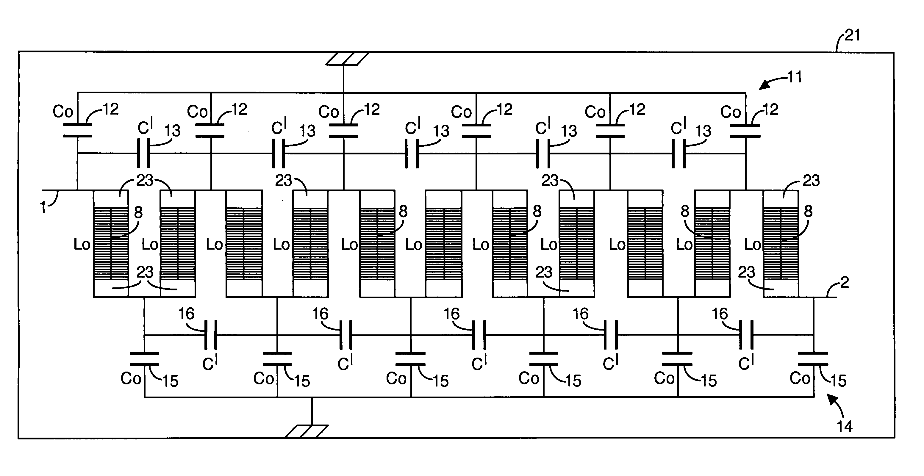
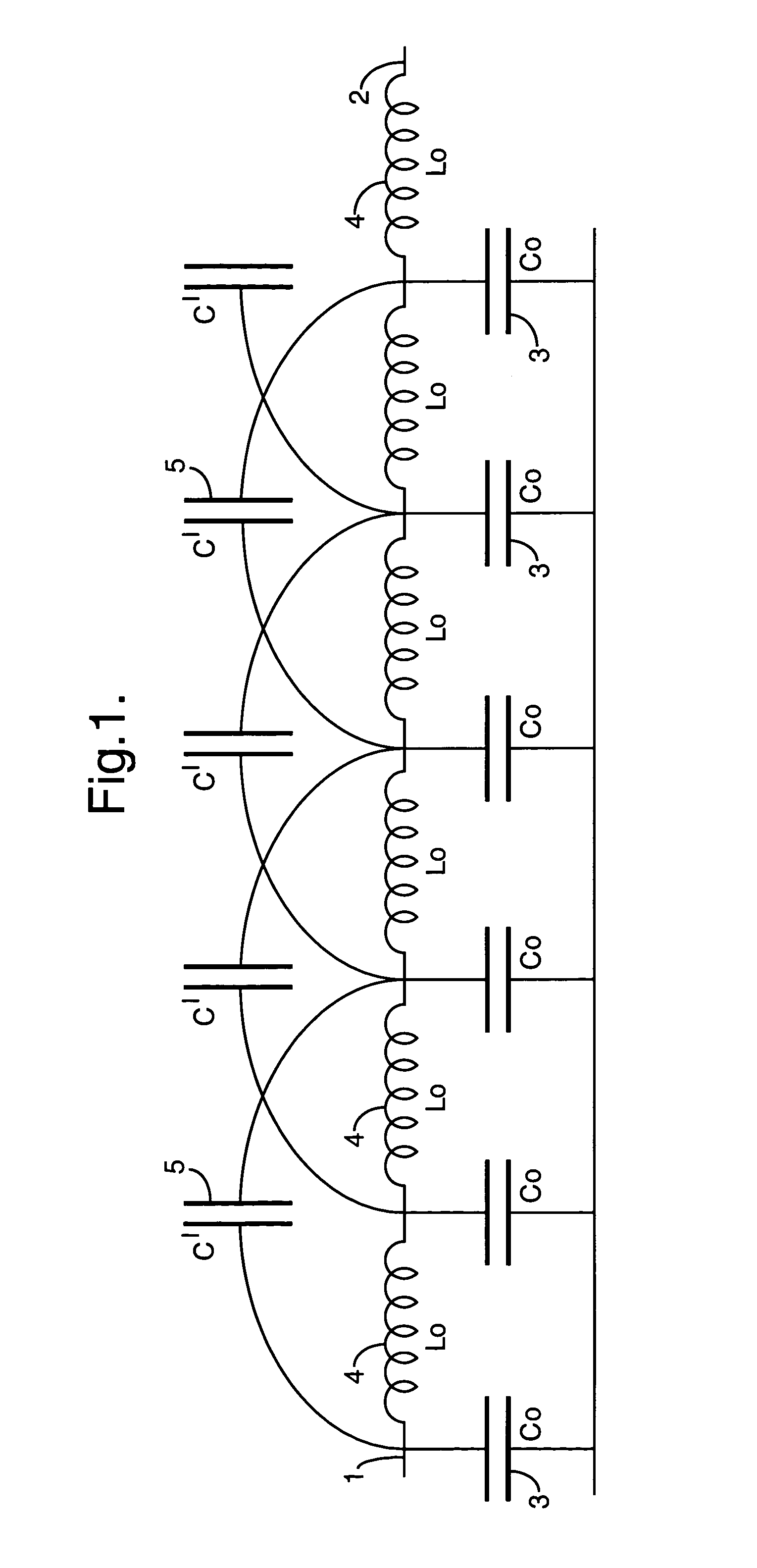
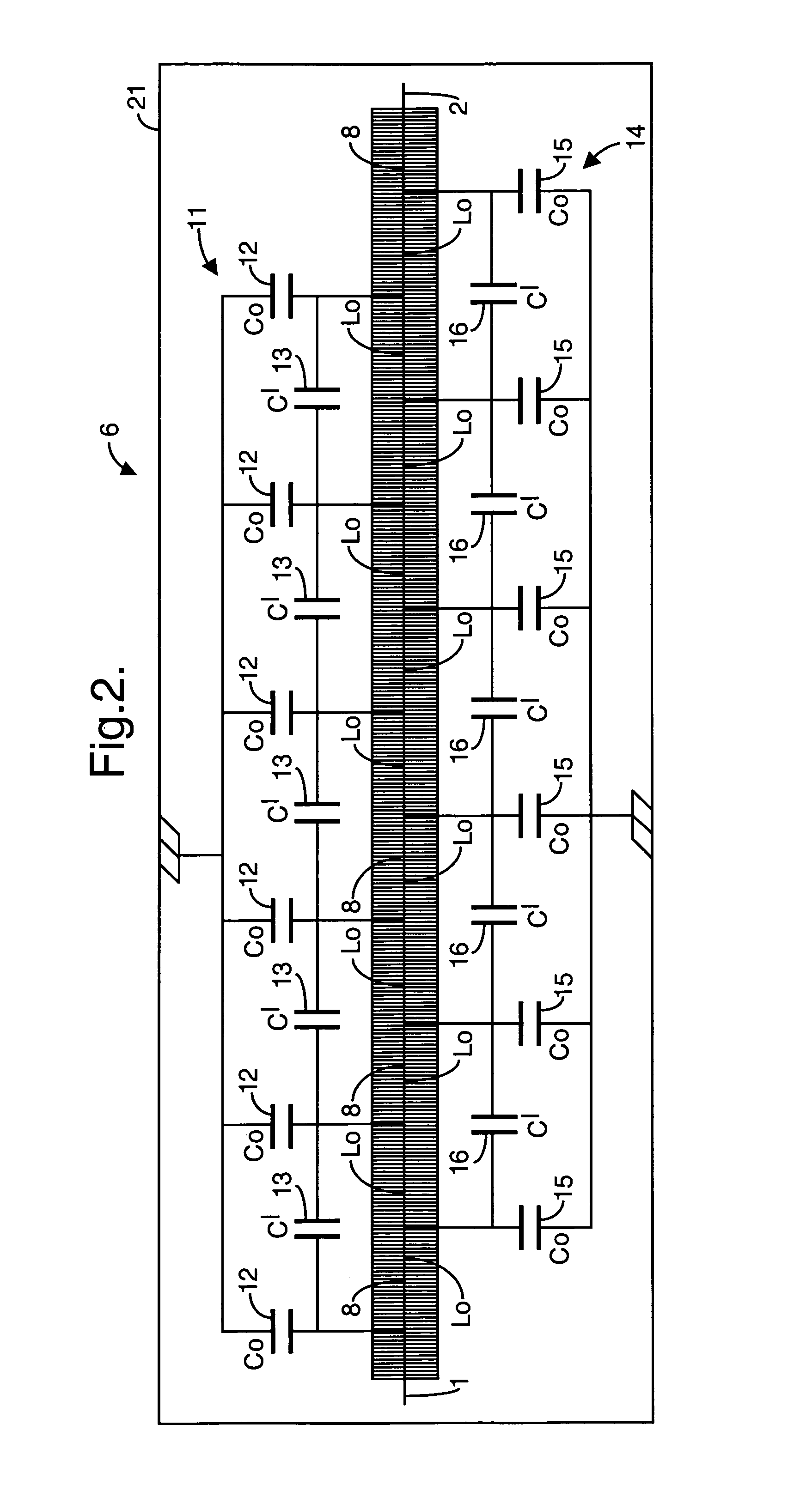
[0029]A non-linear dispersive transmission line assembly according to the present invention is utilised for producing high power radio frequency electrical signals. To this end the assembly includes a transmission line such as shown generally at 6 in FIG. 2 and at 7 in FIG. 5 of the accompanying drawings. Each transmission line includes a plurality of series connected inductors 8 each incorporating saturable magnetic material to provide non-linearity. The inductors 8 may be of any convenient formation. Preferably each inductor comprises ferrite beads 9 threaded on lengths of electrically conductive wire, preferably metal wire, as shown in FIG. 8 of the accompanying drawings or may be a conductive helical winding wound around a magnetic toroid.

[0030]Each transmission line 6, 7 includes a first array 11 of capacitors interconnecting outermost ends of immediately adjacent pairs of the inductors 8. Thus the first array 11 comprises a sub-array of coupling capacitors 12 connected in para...


PUM


Abstract

A non-linear dispersive transmission line assembly for producing high power radio frequency electrical signals includes a transmission line (6, 7) having a plurality of series connected inductors (8) each incorporating saturable magnetic material to provide non-linearity, a first array (11) of capacitors interconnecting outermost ends of immediately adjacent pairs of the inductors (8) and a secondary array (14) of capacitors interconnecting outermost ends of immediately adjacent pairs of the inductors, with the second array interconnection points being spaced by one inductor from the first array interconnection points. The assembly also includes means for applying a first magnetic field to the transmission line (6,7) in a direction substantially perspectively to the direction of a second magnetic field produced in the transmission line by the application thereto of a high voltage input pulse which propagates through the transmission line to form an output high power radio frequency electrical signal.

Description

FIELD OF THE INVENTION[0001]This invention relates to a non-linear dispersive transmission line assembly particularly suitable for producing high power radio frequency electrical signals.BACKGROUND OF THE INVENTION[0002]High power radio frequency and microwave generators are necessary for the production of high power radio frequency signals. With such generators it is necessary to produce peak powers of up to at least 100MW and in this specification the term radio frequency is used to describe radiation in the high frequency, very high frequency, ultra high frequency and microwave regions of the electromagnetic spectrum. It is known that non-linear dispersive transmission lines such as that shown in FIG. 1 of the accompanying drawings, may be used to create radio frequency output pulses by modulation of an electrical impulse input which is injected into the line. Such a line can produce high peak power radio frequency signals with a peak power of more than 100MW. The line of FIG. 1 ...

Claims


Application Information

Patent Timeline
IPC IPC(8): G01S7/282
CPCH03H7/32H03K5/12H03K3/53H03H2001/0057H03K3/45H03K3/80
Inventor SEDDON, NIGEL
Owner BAE SYSTEMS PLC
Why Eureka
Try Eureka