Jitter Buffer Control, Audio Decoder, Method and Computer Program

Active Publication Date: 2016-06-23
FRAUNHOFER GESELLSCHAFT ZUR FOERDERUNG DER ANGEWANDTEN FORSCHUNG EV
View PDF52 Cites 16 Cited by
  • Summary
  • Abstract
  • Description
  • Claims
  • Application Information

AI Technical Summary

Benefits of technology

[0033]In an embodiment, the jitter buffer control is configured to select an overlap-add-operation using a signal-adaptive time shift and a quality control mechanism for a time scaling if a current audio signal portion (or, equivalently, a previous audio signal portion) is active (for example, does not comprise comfort noise generation) and comprises a signal energy which is larger than or equal to the energy threshold value and if the jitter buffer is not empty. The usage of an overlap-add operation using signal-adaptive time shift and a quality control mechanism brings along the advantage that it is possible to avoid intolerable audible artifacts using the quality control mechanism. Thus, the quality control mechanism may, for example, prevent the application of a time scaling, even if the current audio signal portion is active and comprises a signal energy which is larger than or equal to the energy threshold value, and even if a time shifting is requested by a control logic.
[0034]An embodiment according to the invention creates an audio decoder for providing a decoded audio content on the basis of an input audio content. The audio decoder comprises a jitter buffer configured to buffer a plurality of audio frames representing blocks of audio samples. The audio decoder also comprises a decoder core configured to provide blocks of audio samples on the basis of audio frames received from the jitter buffer. The audio decoder also comprises a sample-based time scaler, wherein the sample-based time scaler is configured to provide time-scaled blocks of audio samples on the basis of audio samples provided by the decoder core. Moreover, the audio decoder comprises a jitter buffer control, as described above. The jitter buffer control is configured to select a frame-based time scaling, which is performed by the jitter buffer, or a sample-based time scaling, which is performed by the sample-based time scaler, in a signal-adaptive manner. Accordingly, two substantially different time scaling concepts are selected by the jitter buffer control, wherein the frame based time scaling is performed before audio frames are input into the decoder core (for example, by adding or removing entire audio frames), and wherein the sample-based time scaling is performed on the basis of blocks of audio samples provided by the decoder core. Thus, a selection is made between two substantially different time scaling approaches in a signal-adaptive manner, which allows for an adaptation of the time scaling mode to the signal, and which consequently brings along a good efficiency while avoiding excessive audible artifacts (or distortions).
[0035]In an embodiment, the jitter buffer is configured

Problems solved by technology

A particular challenge is caused by the fact that a listener expects a continuous playback of audio contents, without any interruptions and also without any audible artifacts caused by the storage and/or transmission of the audio content.
Problems arise, for example, if a readout from a storage medium is temporarily interrupted or delayed, or if a transmission between a data source and a data sink is temporarily interrupted or delayed.
For example, a transmission via the internet is not highly reliable, since TCP/IP packets may be lost, and since the transmission delay over the internet may vary, for example, in dependence on the varying load situation of the internet nodes.
However, it has been found that a time scalin

Method used


Image

  • Jitter Buffer Control, Audio Decoder, Method and Computer Program
  • Jitter Buffer Control, Audio Decoder, Method and Computer Program
  • Jitter Buffer Control, Audio Decoder, Method and Computer Program

Examples


Embodiment Construction

5.1. Jitter Buffer Control According to FIG. 1

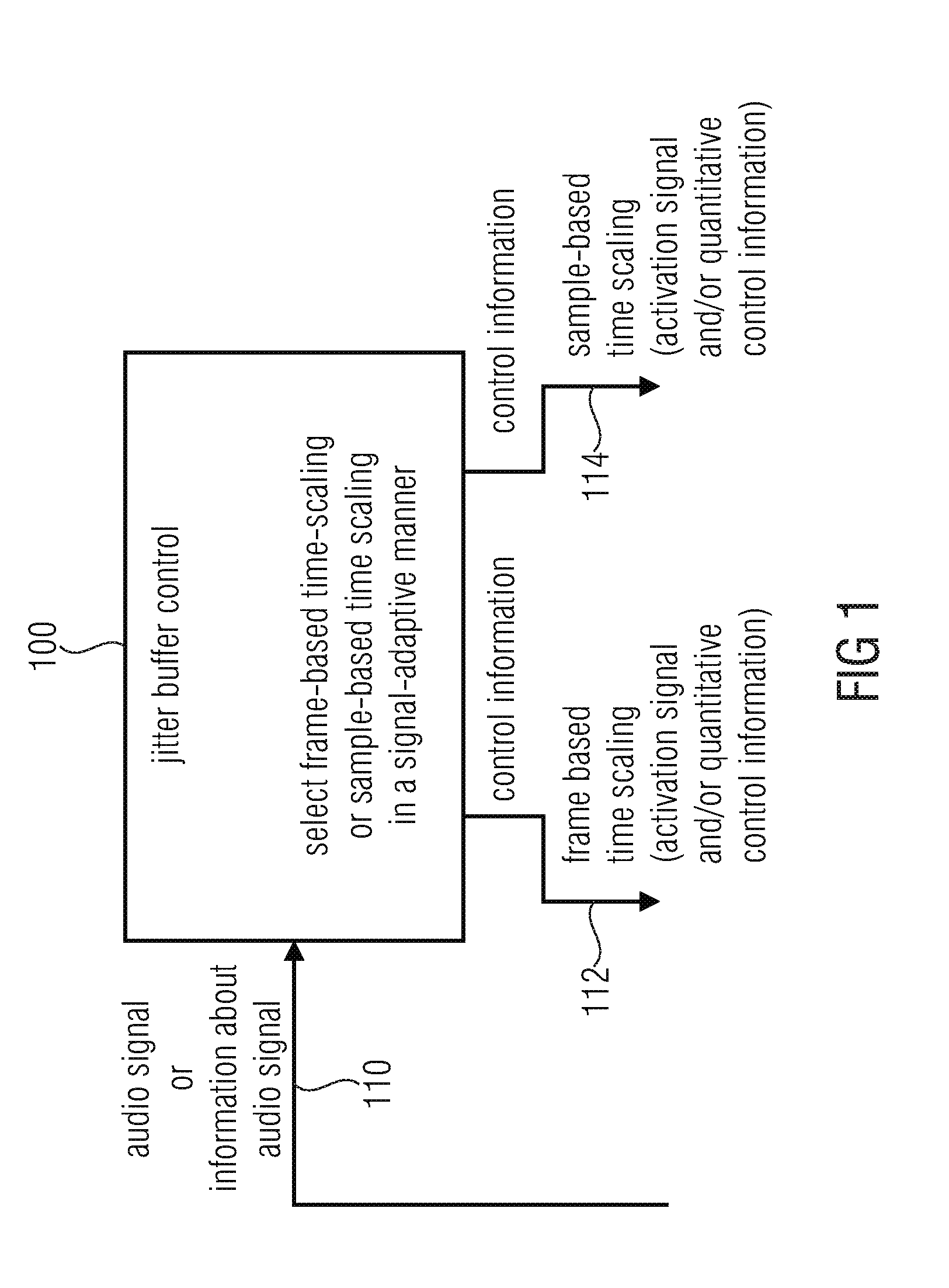
[0056]FIG. 1 shows a block schematic diagram of a jitter buffer control, according to an embodiment of the present invention. The jitter buffer control 100 for controlling a provision of a decoded audio content on the basis of an input audio content receives an audio signal 110 or an information about an audio signal (which information may describe one or more characteristics of the audio signal, or of frames or other signal portions of the audio signal).

[0057]Moreover, the jitter buffer control 100 provides a control information (for example, a control signal) 112 for a frame-based scaling. For example, the control information 112 may comprise an activation signal (for the frame-based time scaling) and / or a quantitative control information (for the frame-based time scaling).

[0058]Moreover, the jitter buffer control 100 provides a control information (for example, a control signal) 114 for the sample-based time scaling. The control infor...


PUM


Abstract

A jitter buffer control for controlling a provision of a decoded audio content on the basis of an input audio content is configured to select a frame-based time scaling or a sample-based time scaling in a signal-adaptive manner. An audio decoder uses such a jitter buffer control.

Description

CROSS-REFERENCE TO RELATED APPLICATIONS[0001]This application is a continuation of copending International Application No. PCT / EP2014 / 062789, filed Jun. 18, 2014, which is incorporated herein by reference in its entirety, and additionally claims priority from European Application No. 13173159.8, filed Jun. 21, 2013, and from European Application No. 14167061.2, filed May 5, 2014, which are also incorporated herein by reference in their entirety.BACKGROUND OF THE INVENTION[0002]Embodiments according to the invention are related to a jitter buffer control for controlling a provision of a decoded audio content on the basis of an input audio content.[0003]Further embodiments according to the invention are related to an audio decoder for providing a decoded audio content on the basis of an input audio content.[0004]Further embodiments according to the invention are related to a method for controlling a provision of a decoded audio content on the basis of an input audio content.[0005]Furt...

Claims


Application Information

Patent Timeline
IPC IPC(8): G10L19/022G10L19/012G10L19/04H04L49/9023
CPCG10L19/022G10L19/012G10L19/04G10L21/04H04J3/0632H04J3/0664H04J3/06
Inventor REUSCHL, STEFANDOEHLA, STEFANLECOMTE, JEREMIEJANDER, MANUEL
Owner FRAUNHOFER GESELLSCHAFT ZUR FOERDERUNG DER ANGEWANDTEN FORSCHUNG EV
Why Eureka
Try Eureka