Power reception control device, power transmission control device, non-contact power transmission system, power reception device, power transmission device, and electronic instrument
a technology of power transmission control and power reception device, which is applied in the direction of pulse characteristics measurement, instruments, pulse techniques, etc., can solve the problems of product fire, product burn, and disadvantage of technology
- Summary
- Abstract
- Description
- Claims
- Application Information
AI Technical Summary
Problems solved by technology
Method used
Image
Examples
first embodiment
[0124]Examples of an electronic instrument to which the invention is suitably applied and the principle of non-contact power transmission technology are described below.
[0125]Examples of electronic instrument and principle of non-contact power transmission
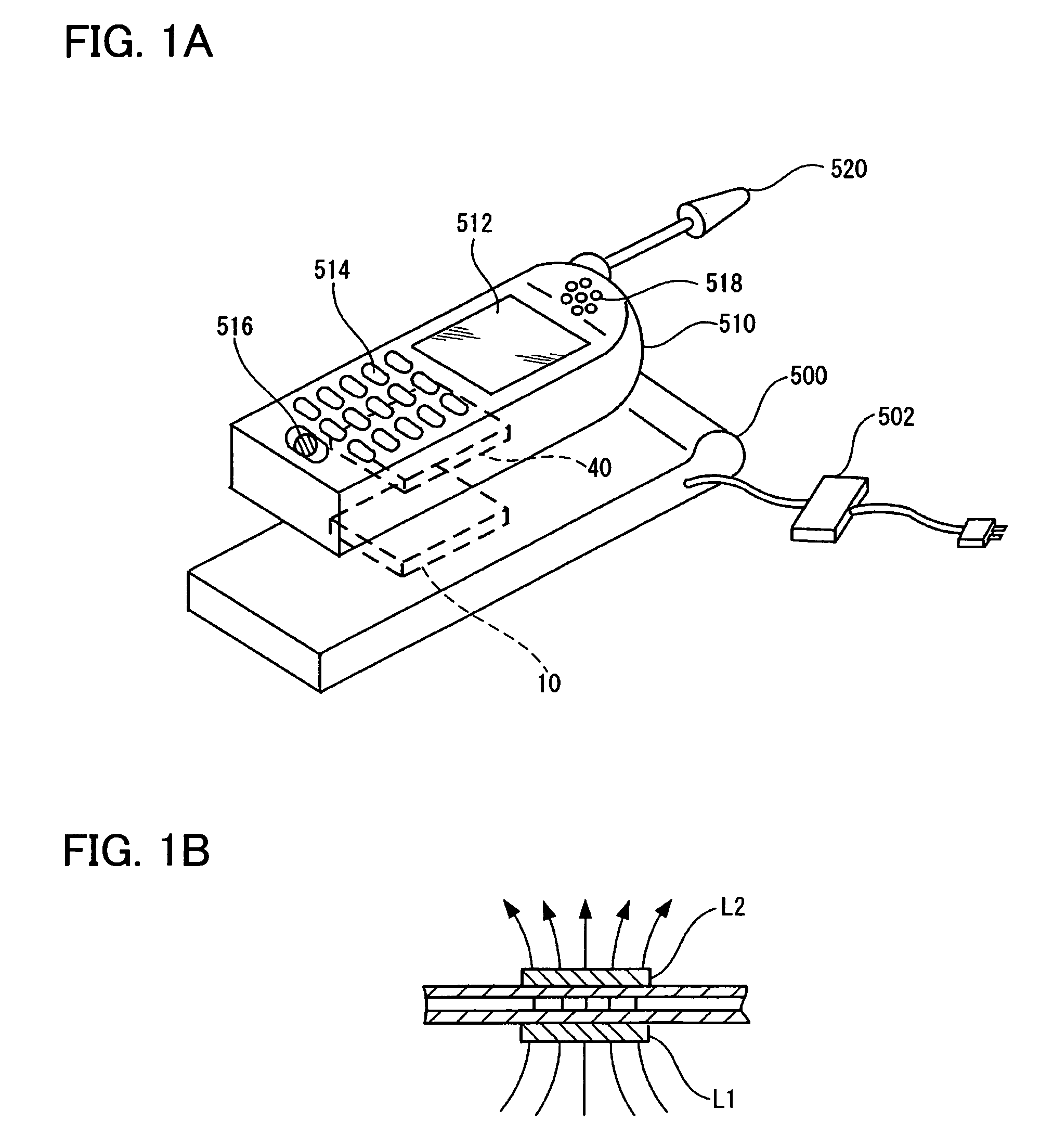
[0126]FIGS. 1A and 1B are views illustrative of non-contact power transmission technology. FIG. 1A is a view showing examples of an electronic instrument to which non-contact power transmission is applied. FIG. 1B is a view illustrative of the principle of non-contact power transmission using an induction transformer.
[0127]As shown in FIG. 1A, a charger 500 (cradle) (i.e., electronic instrument) includes a power transmission device 10. A portable telephone 510 (i.e., electronic instrument) includes a power reception device 40. The portable telephone 510 also includes a display section 512 such as an LCD, an operation section 514 which includes a button or the like, a microphone 516 (sound input section), a speaker 518 (sound output...
second embodiment
[0191]This embodiment illustrates a specific configuration and operation suitable for detecting insertion of a foreign object.
[0192]Specific example of foreign object insertion detection
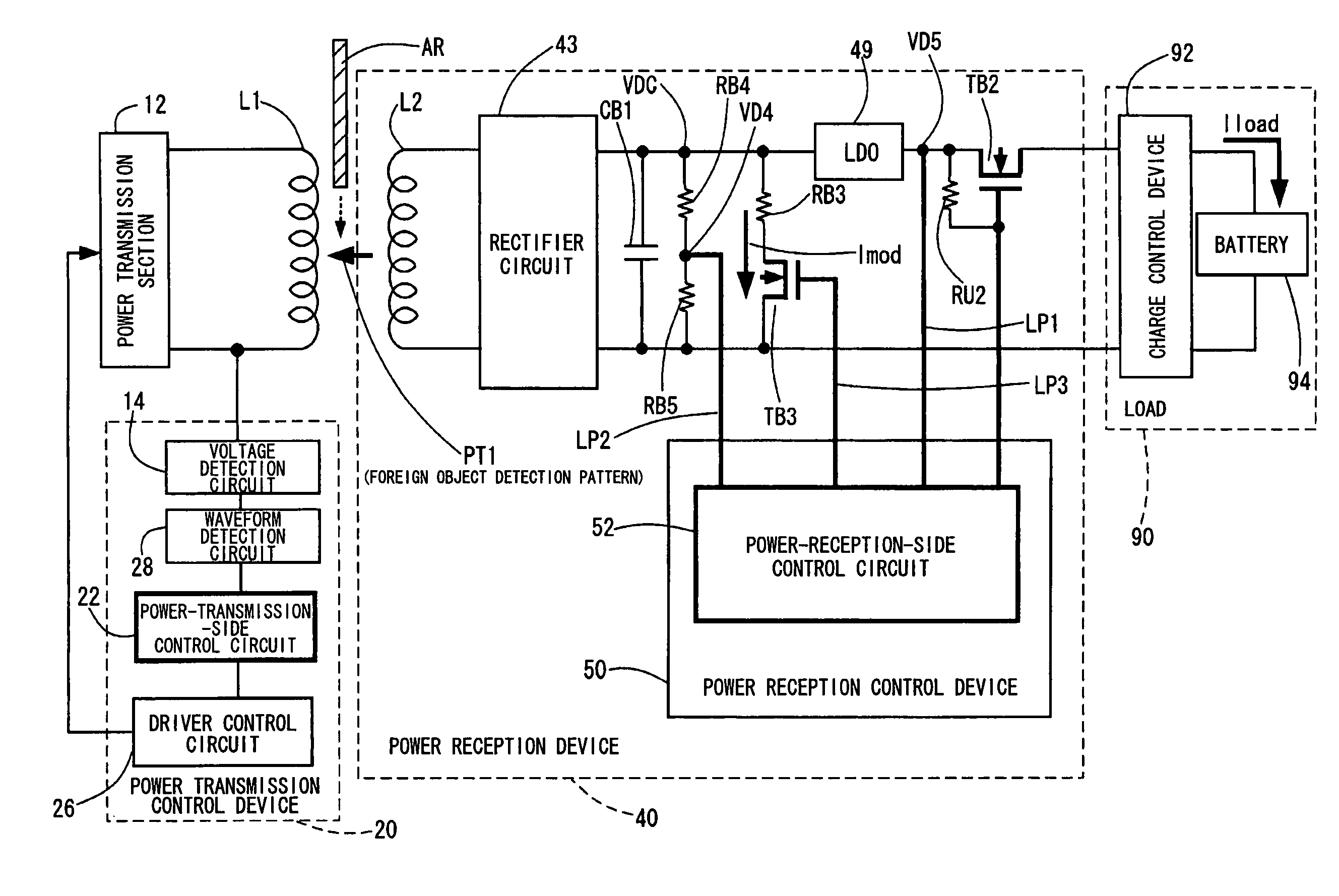
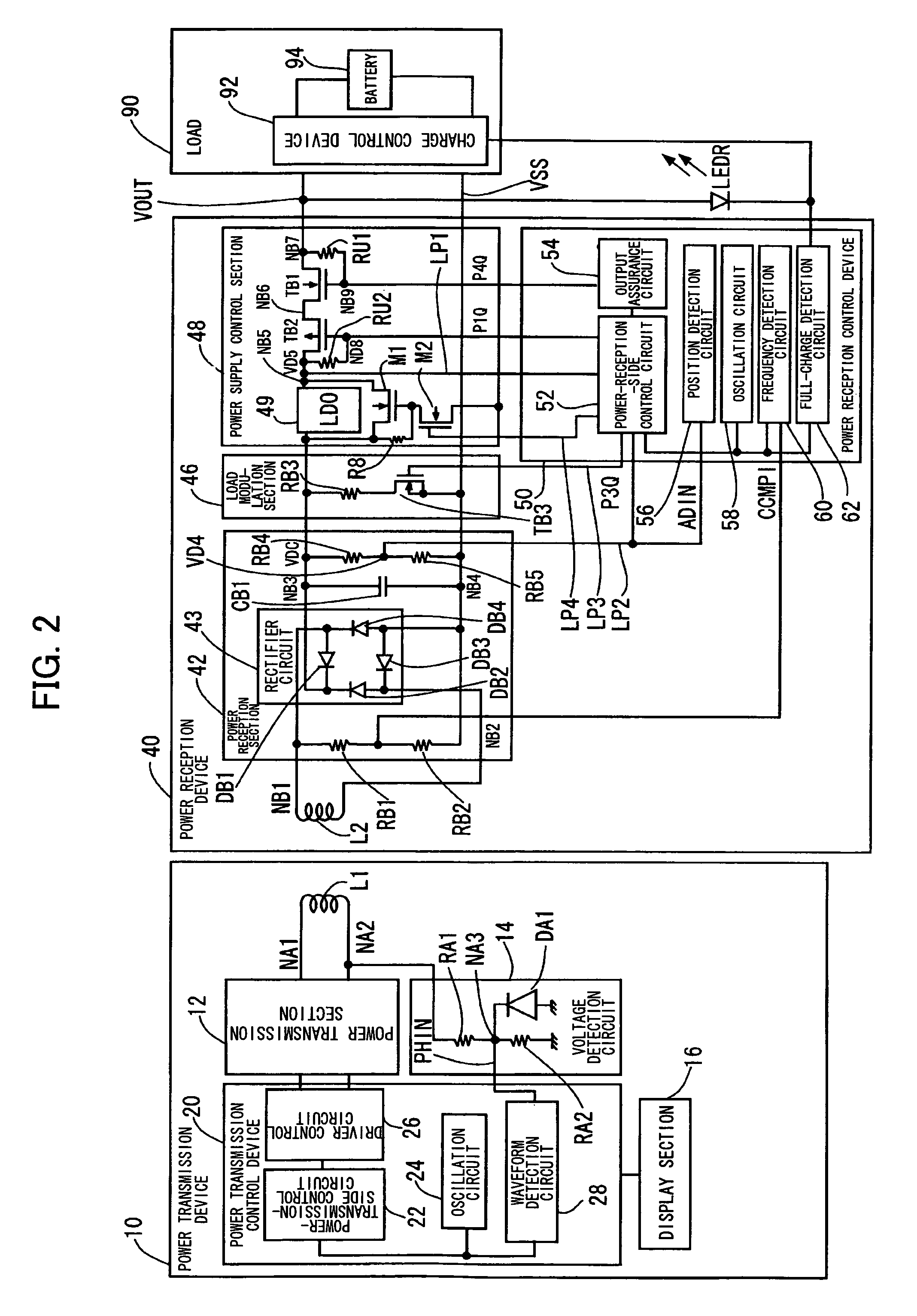
[0193]FIG. 7 is a circuit diagram showing the main configuration of the non-contact power transmission system shown in FIG. 2 relating to detection of insertion of a foreign object. In FIG. 7, the same sections as in FIG. 2 are indicated by the same reference symbols. In FIG. 7, a bold line indicates a portion that plays an important role in detecting insertion of a foreign object.
[0194]A notable circuit configuration of the power reception device 40 shown in FIG. 7 includes the load modulation transistor TB3 of the load modulation section 46 (see FIG. 2), the power supply control transistor TB2 of the power supply control section 48 (see FIG. 2), and the power-receiving-side control circuit 52 which ON / OFF-controls these transistors (TB2 and TB3). It is also important that the voltages at the input ...
PUM
 Abstract
Description
Claims
Application Information
 - R&D
- Intellectual Property
- Life Sciences
- Materials
- Tech Scout
- Unparalleled Data Quality
- Higher Quality Content
- 60% Fewer Hallucinations
Browse by: Latest US Patents, China's latest patents, Technical Efficacy Thesaurus, Application Domain, Technology Topic, Popular Technical Reports.
© 2025 PatSnap. All rights reserved.Legal|Privacy policy|Modern Slavery Act Transparency Statement|Sitemap|About US| Contact US: help@patsnap.com


