Trigger type pump dispenser

a pump dispenser and trigger technology, applied in the direction of liquid transfer devices, single-unit apparatuses, transportation and packaging, etc., can solve the problems of poor transmission efficiency of power, complex structure around the trigger, and inability to reach the right location of jetted liquid, so as to achieve efficient and smooth channel passage, less failure, and simple structure

Active Publication Date: 2011-11-29
CANYON
View PDF16 Cites 22 Cited by
  • Summary
  • Abstract
  • Description
  • Claims
  • Application Information

AI Technical Summary

Benefits of technology

[0037]In the trigger-type pump dispenser of the present invention, the coupling part of the piston structure can be bent, and the many fins are formed on the periphery thereof so that the interior channel is not deformed; therefore, the jetted liquid can efficiently and smoothly pass through the channel.
[0038]Moreover, the coupling part has the bendable structure that absorbs the vertical movement of the piston; therefore, extra parts are not required, the structure is simple, and less failure is caused.
[0039]Moreover, the coupling part of the piston structure can be bent by an angle of 90 degrees or more; therefore, the piston structure can be inject-molded in a linear state and then can be bent and assembled.
[0040]As a result, the piston structures as many as possible can be formed from the molds having a certain size.
[0041]Moreover, the rod-like closing valve which blocks the pressure in the container by sealing the channel in the piston part at the top dead point of the piston part is provided in the cylinder part; therefore, leakage from the nozzle part does not occur even when the pressure in the container main body is increased for some reasons and the liquid back-flows in the cylinder part.
[0042]Moreover, the rod-like closing valve is integrally formed with the first valve upon manufacturing and, upon use, separated and subjected to use; therefore, the number of parts is reduced.

Problems solved by technology

In this manner, the structure in which the nozzle part is vertically moved has drawbacks that the nozzle cannot set a target on the location serving as a jetting target and that the jetted liquid cannot reach a right location.
However, this trigger-type pump dispenser does not directly transmit the movement of the trigger to the piston.
More specifically, since the trigger transmits the movement thereof to the piston via a swing lever, the structure around the trigger becomes complex, and transmission efficiency of power is bad from the viewpoint of friction force.
In addition, since the number of parts is large, assembling man-hours are increased, and failure readily occurs.
Therefore, the liquid does not efficiently pass through the channel in some cases.

Method used


Image

  • Trigger type pump dispenser
  • Trigger type pump dispenser
  • Trigger type pump dispenser

Examples


Embodiment Construction

[0046]Hereinafter, a best mode for carrying out the present invention will be explained based on drawings.

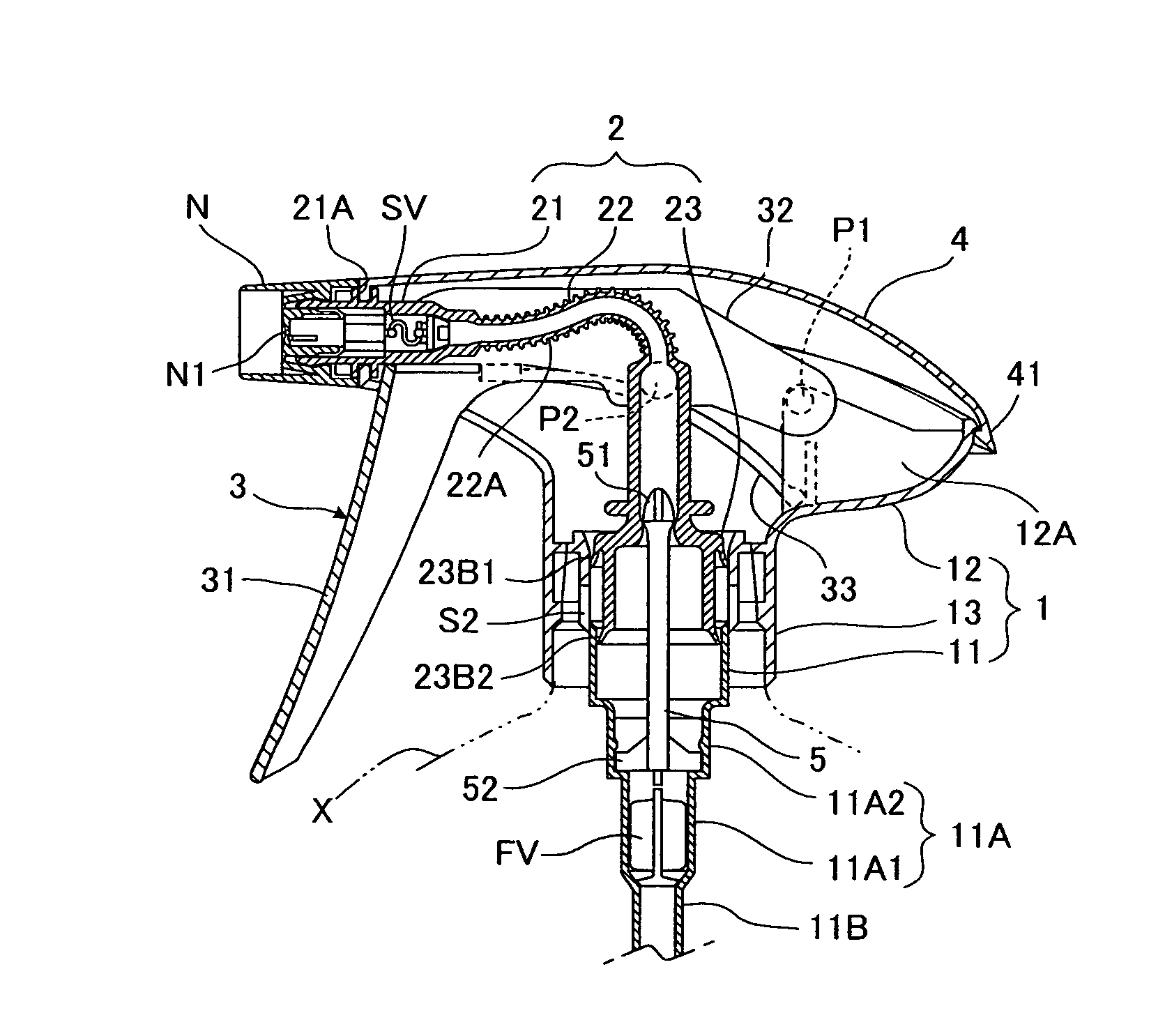
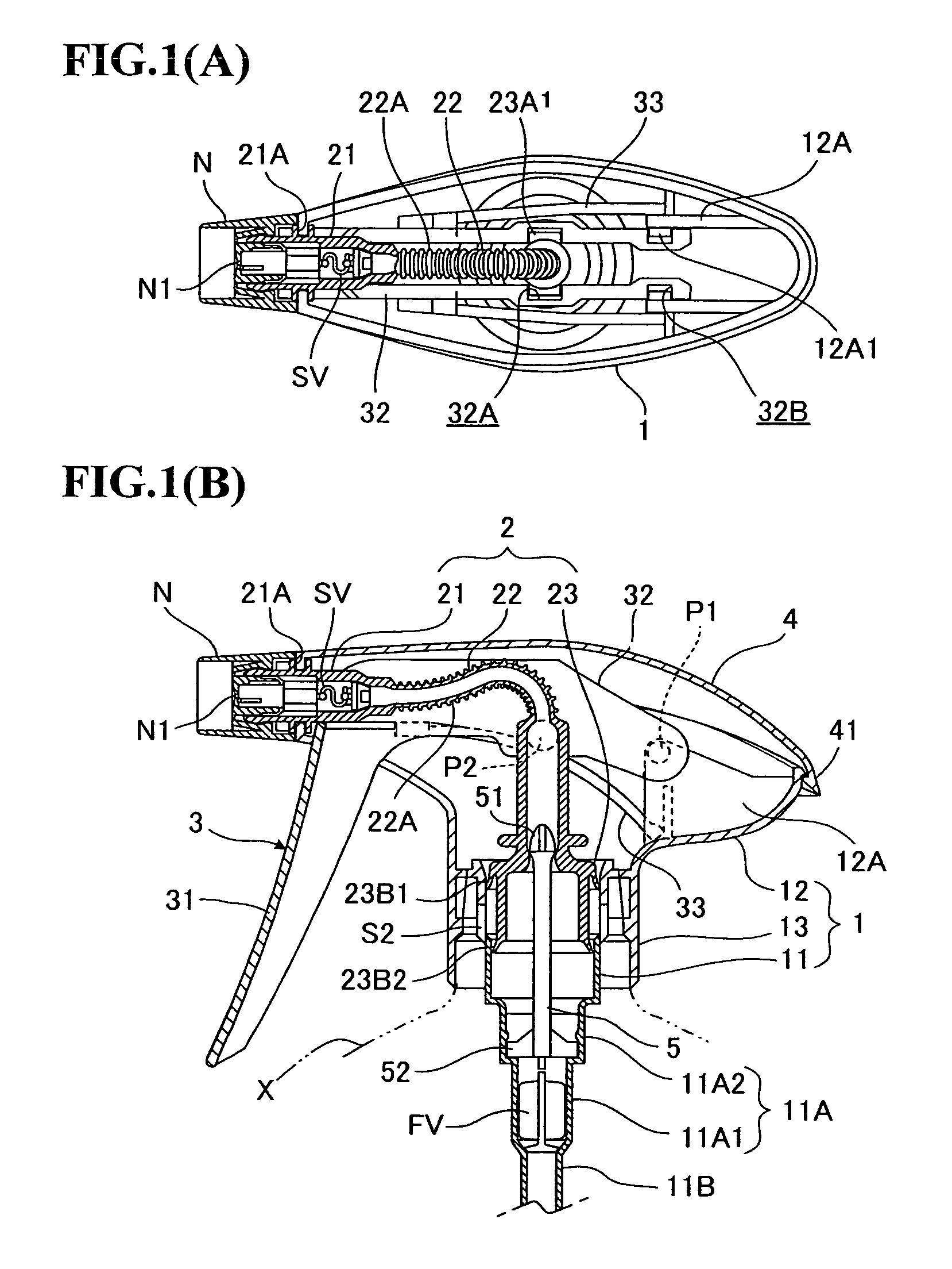
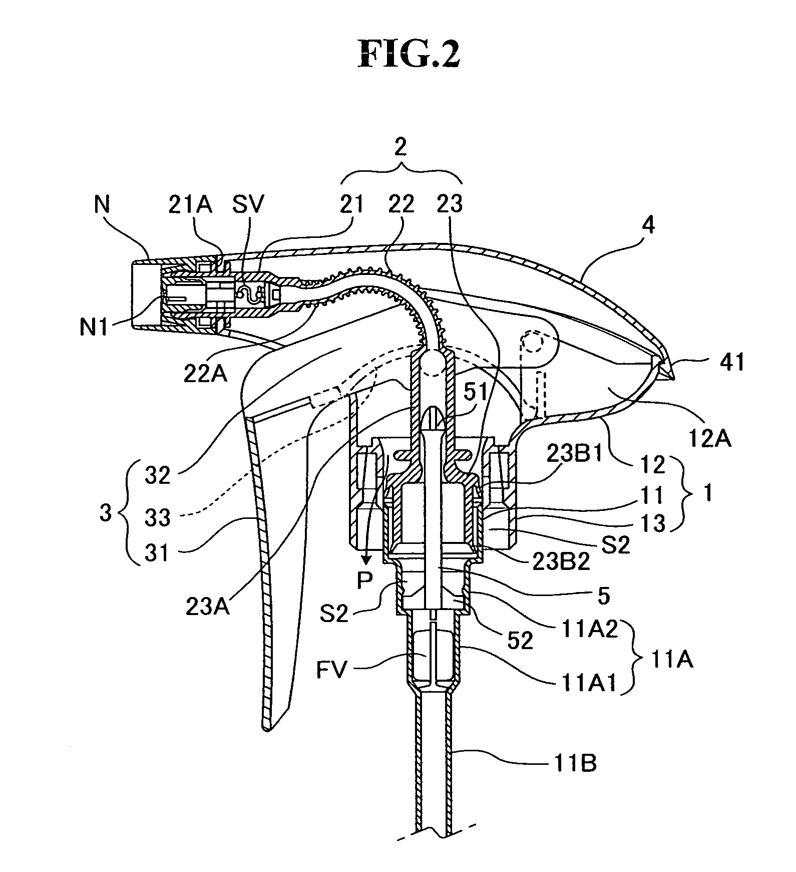
[0047]FIGS. 1A and 1B and FIG. 2 are drawings showing a trigger-type pump dispenser according to an embodiment of the present invention and are showing the states before pulling and after pulling a trigger 3, respectively.

[0048]The trigger-type pump dispenser slides a piston part 23 downward and jets liquid in a cylinder from a nozzle part 21 when the trigger 3 is pulled, in other words, turned as shown in FIG. 2.

[0049]In the trigger-type pump dispenser of the present invention, at this point, the position of the nozzle part 21 is not changed at all and is not vertically moved.

[0050]The trigger-type pump dispenser has, a base main body 1 which, first, directly attached to a container, a cover body 4 which is attached to the base main body 1, the trigger 3 which is attached to the base main body 1, and a piston structure 2 which is vertically moved by the trigger 3; and an interi...


PUM


Abstract

A trigger-type pump dispenser capable of preventing deformation of a channel of a coupling part when a piston is vertically pushed down by a trigger even in a structure in which the coupling part bends and a nozzle does not vertically move. The dispenser has a base main body 1 having the cylinder part 11 inside and attachable to an opening part of a container main body. A cover body 4 detachably latched with the base main body. A piston structure 2 composed of the nozzle part 21 engaged with the base main body, the piston part 23, and a bendable coupling part coupling the nozzle part and the piston part. Many fins 22A are formed on the periphery of the coupling part 22 so that an interior channel is not deformed.

Description

TECHNICAL FIELD[0001]The present invention relates to a trigger-type pump dispenser which is free from vertical movement of a nozzle part and facilitates pointing at a target upon jetting.[0002]More particularly, the present invention relates to a trigger-type pump dispenser which jets liquid in a cylinder from the nozzle part to outside by vertically sliding a piston member, wherein the trigger-type pump dispenser is capable of precisely hitting a position serving as a target by the liquid in the state in which there is completely no vertical movement of the nozzle part and has a simple structure.[0003]Conventionally, a trigger-type pump dispenser has been used as a means which jets liquid such as a chemical solution to a predetermined part.[0004]The pump dispenser has advantages that a piston is moved merely by operating a trigger so as to readily jet liquid, which is in a container connected to a cylinder, from a nozzle and is widely used.[0005]In such a trigger-type pump dispens...

Claims


Application Information

Patent Timeline
Patent Type & Authority Patents(United States)
IPC IPC(8): B67D7/58F16L11/00B05B11/00
CPCB05B11/3011B05B11/1011
Inventor TADA, TETSUYA
Owner CANYON
Why Eureka
Try Eureka