Failsafe thermal bypass valve for cooling system

a technology of thermal bypass valve and cooling system, which is applied in the direction of machines/engines, process and machine control, instruments, etc., can solve problems such as substantial damage to machines or vehicles

Active Publication Date: 2011-11-29
DANA CANADA CORP
View PDF9 Cites 23 Cited by
  • Summary
  • Abstract
  • Description
  • Claims
  • Application Information

AI Technical Summary

Benefits of technology

[0005]According to one embodiment of a thermal bypass valve for a heat exchanger circuit, the bypass valve comprises a valve housing forming a valve chamber including a bypass passage and having a first port for flow of a heat exchange fluid into the valve chamber, a second port for flow of the heat exchange fluid out of the valve chamber, a third port for flow of heat exchange fluid from the valve chamber to a heat exchanger, a fourth port for flow of the heat exchange fluid from the heat exchanger to the valve chamber, and a bypass port defined by a valve seat provided in the housing. Axially aligned first and second thermally sensitive actuators are mounted in the chamber, are connected to one another, and have respective first and second actuator bodies and respective first and second movable pistons each extendible from one end of its respective actuator body. At least one of the actuator bodies is normally movable in the valve chamber in response to extension of its piston. One of the actuators is adapted to extend its position at a selected higher temperature than a pre-determined temperature required for the other actuator to extend its respective piston. There is also a valve member mounted on one of the first and second actuators which is adjacent the valve seat and movable by either the first or the second actuator from a first position, where the bypass port is in an open state, to a closed position where the bypass port is closed by the valve member engaging the valve seat. A return spring mechanism is mounted in the housing and is adapted to bias an adjacent one of the actuators away from the valve seat. The bias of the return spring mechanism can be overcome during use of the bypass valve by extension of either the first piston or the second piston depending on the temperature to which the actuator bodies are heated.

Problems solved by technology

A possible deficiency with known oil cooler bypass valves is that, if they fail to operate as designed, this can result in substantial damage occurring to the machine or vehicle which requires the oil or heat exchange fluid to be within a desired temperature range in order to operate or in order to operate without undue wear.

Method used


Image

  • Failsafe thermal bypass valve for cooling system
  • Failsafe thermal bypass valve for cooling system
  • Failsafe thermal bypass valve for cooling system

Examples


Embodiment Construction

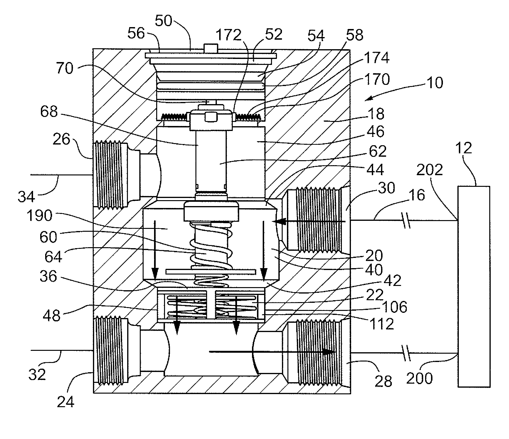
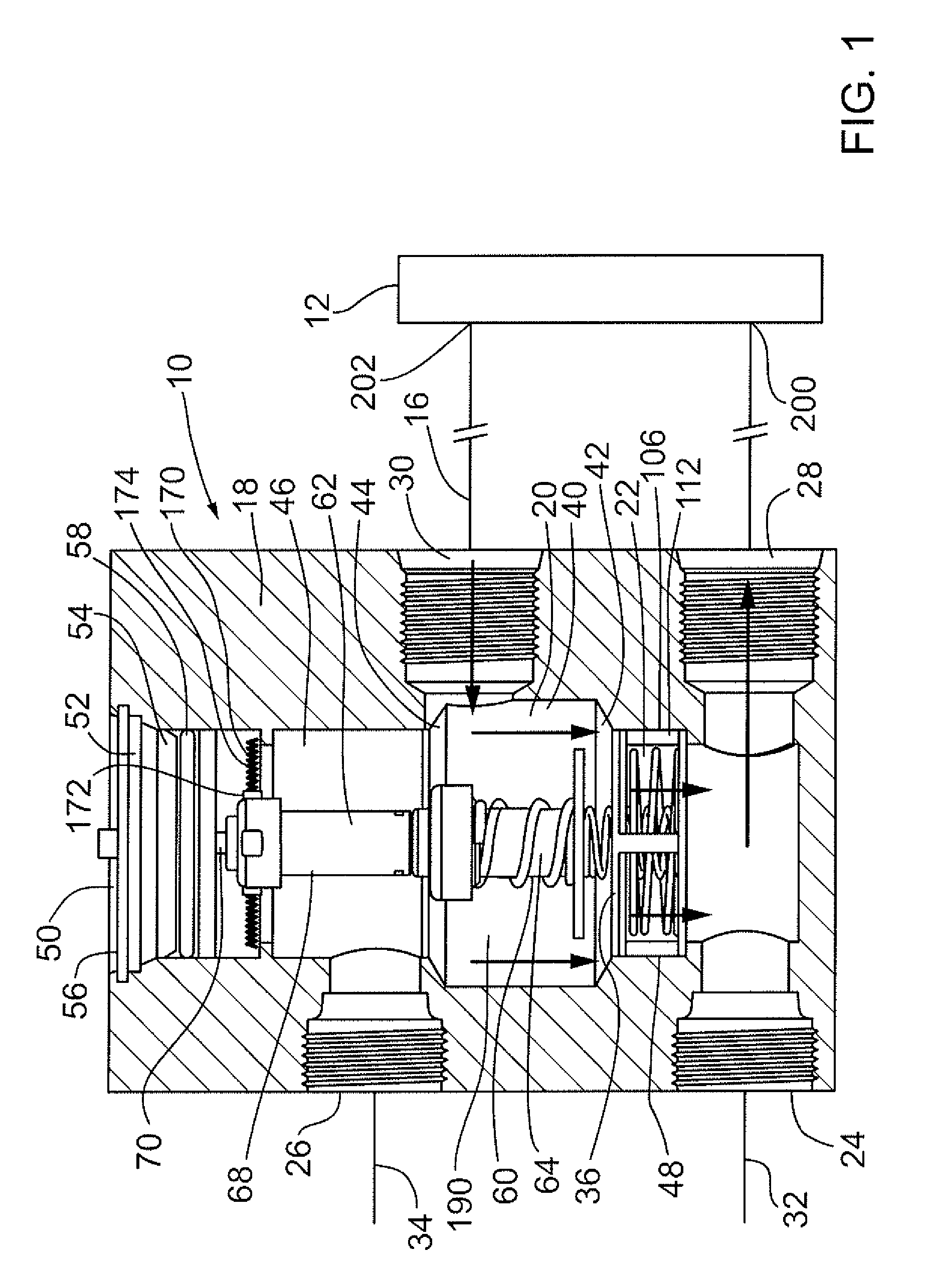
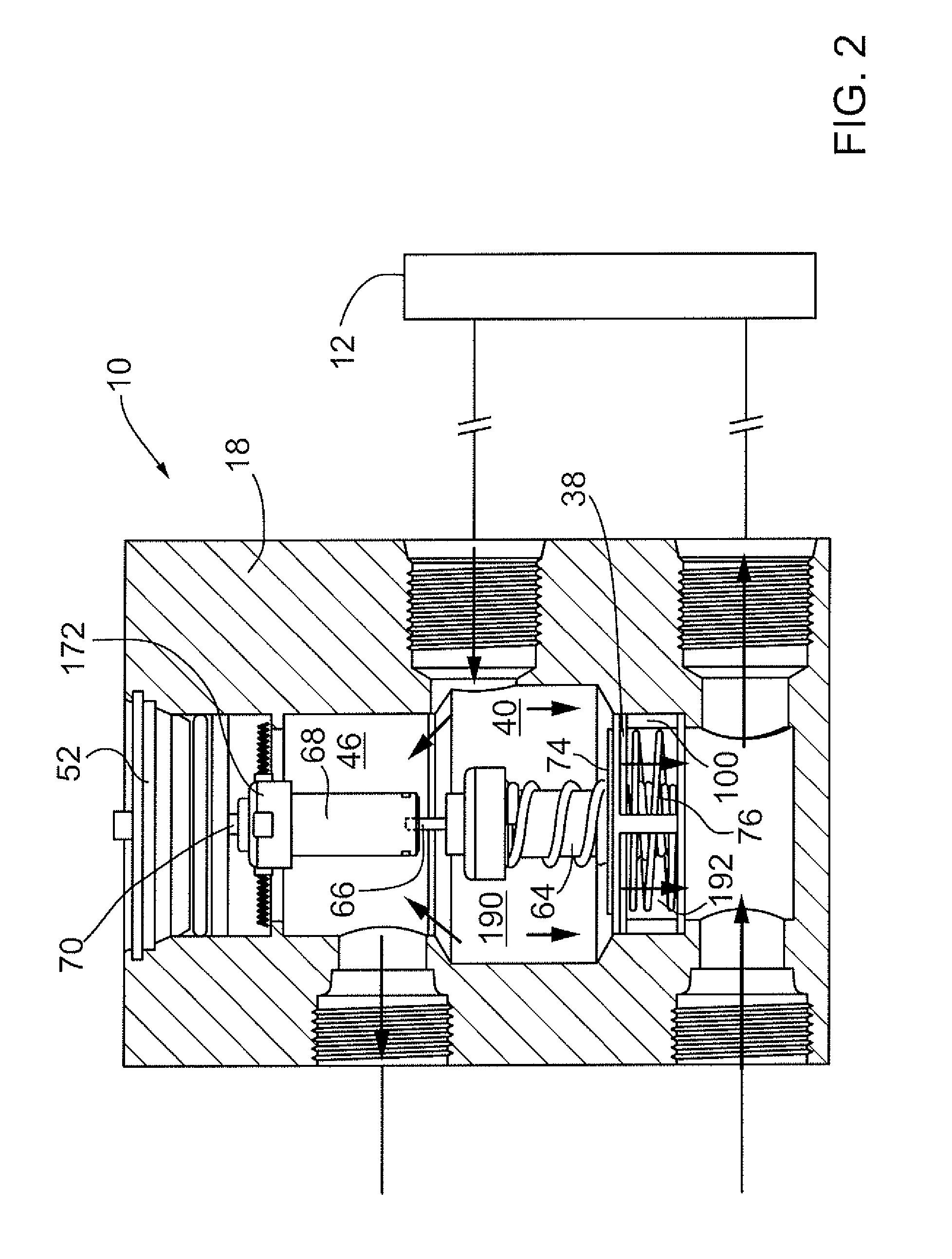
[0044]With reference to FIGS. 1 to 3, there is shown an example of a thermal bypass valve indicated generally be reference 10 which can be used in a heat exchanger circuit to control the flow of a fluid, such as transmission fluid to a heat exchanger 12 to which first and second conduits 14 and 16 are connected. The heat exchanger can be a cooler or cooler unit of standard construction if it is being used to cool transmission fluid or transmission oil. The bypass valve has a valve housing indicated generally by reference 18 which forms a valve chamber 20 that includes a bypass passage 22. The illustrated bypass valve housing has a first port 24 for flow of the heat exchange fluid i.e. transmission fluid into the valve chamber, a second port 26 for the flow of the heat exchange fluid out of the valve chamber, a third port 28 for the flow of the heat exchange fluid from the valve chamber to the heat exchanger 12, and a fourth port 30 for the flow of heat exchange fluid from the heat e...


PUM


Abstract

A thermal bypass valve for a heat exchanger circuit includes a valve housing forming a valve chamber including a bypass passage and ports for the flow of heat exchange fluid into and out of the valve chamber as well as a bypass port defined by a valve seat. Two axially aligned thermally sensitive actuators are mounted in the chamber, each with an actuator body and its own movable piston extendible from one end of the body. One of these pistons operably engages the actuatory body associated with the other piston. Each actuator body is normally movable in the chamber in response to extension of its piston. One of the actuators extends its piston at a higher temperature than the temperature required for the other actuator to extend its piston. A bypass valve member is mounted on one of the actuators and can be moved by either actuator from an open position to a closed position.

Description

BACKGROUND OF THE INVENTION[0001]This invention relates to thermal bypass valves for a heat exchanger circuit and a heat exchanger system using this type of valve.[0002]Thermal bypass valves are well known in the art of heat exchangers. In particular such valves are commonly used with an oil cooler in order to help regulate the temperature of oil used in engines, transmissions, power steering systems and hydraulic systems. These known valves can provide a flow path by which the oil or heat exchange fluid passing to the valve from an oil source is returned without passing through a heat exchanger or oil cooler during a warm-up period.[0003]An example of an oil cooler bypass valve is that taught in U.S. Pat. No. 6,935,569 which issued Aug. 30, 2005. This known cooler bypass valve has a responsive element that expands to urge a valve member against a valve seat and thereby causes transmission fluid to flow through an oil fluid cooler. A cast valve housing is utilized which is interpose...

Claims


Application Information

Patent Timeline
Patent Type & Authority Patents(United States)
IPC IPC(8): G05D23/08F01P7/14F01P7/02G05D23/00
CPCF01P7/16G05D23/1333F16K31/002
Inventor SHEPPARD, JEFFREY OWEN
Owner DANA CANADA CORP
Why Eureka
Try Eureka