Intervertebral Implant Assembly and Instruments Therefor

Pending Publication Date: 2020-09-10
K2M
View PDF5 Cites 5 Cited by
  • Summary
  • Abstract
  • Description
  • Claims
  • Application Information

AI Technical Summary

Benefits of technology

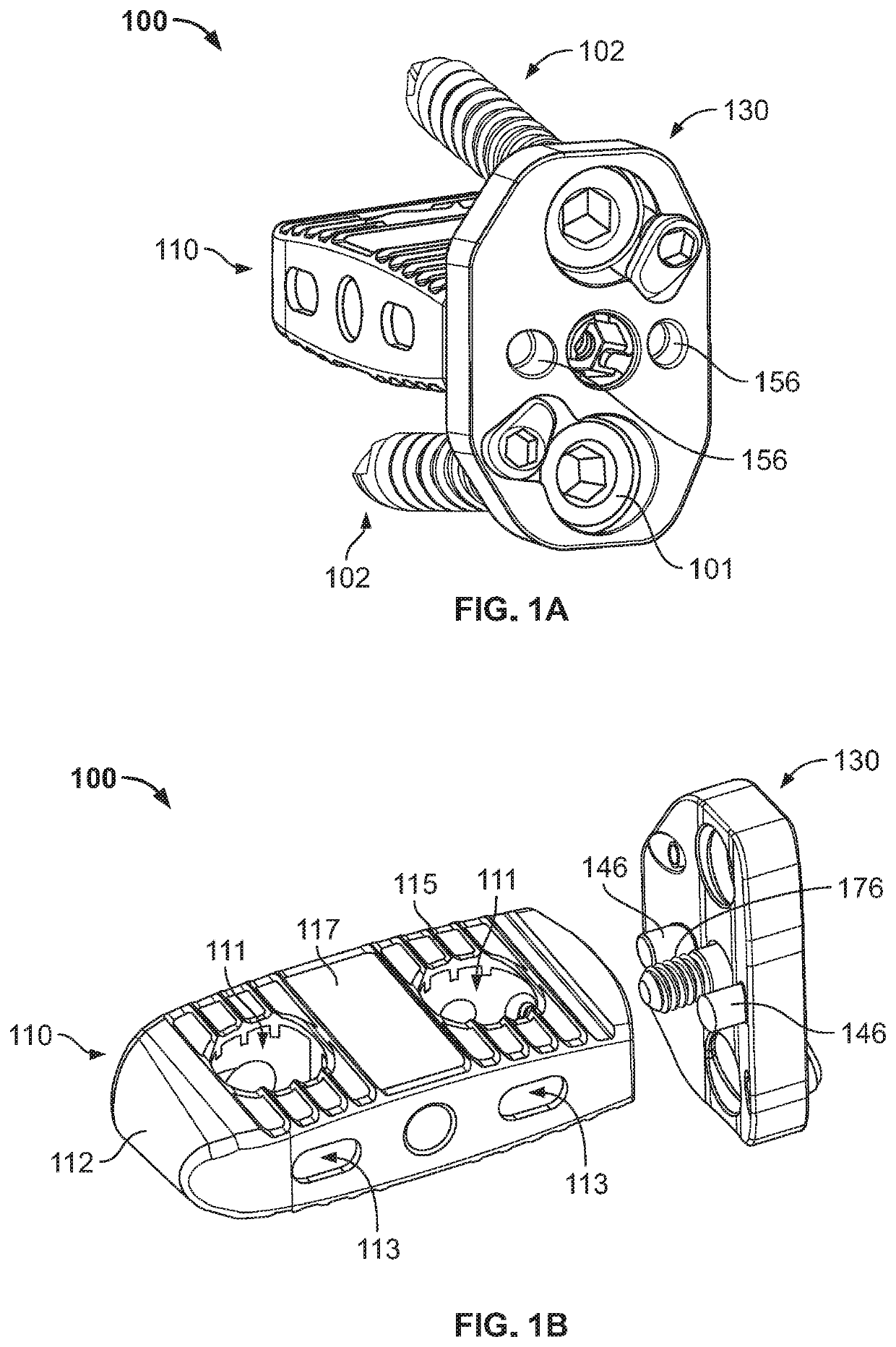
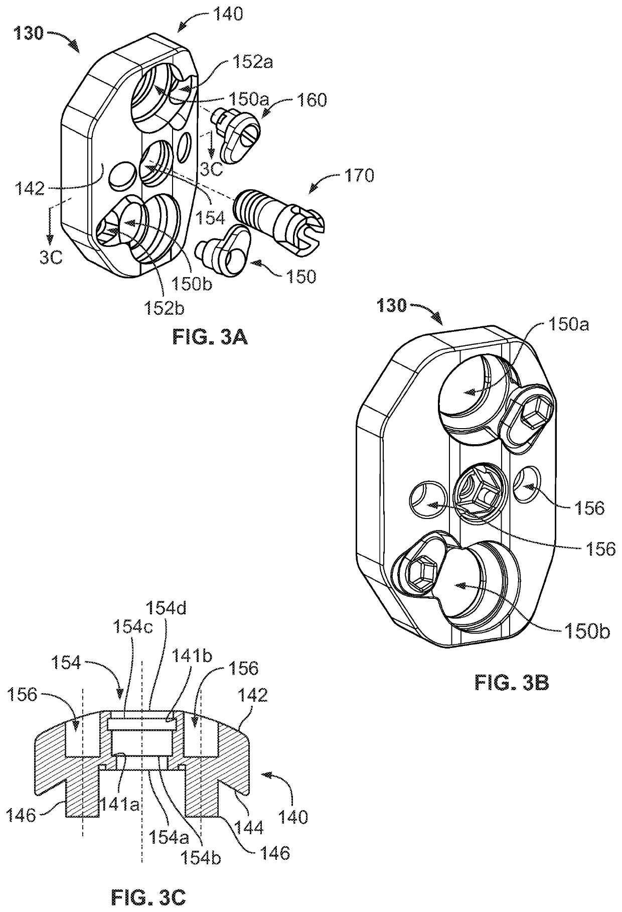
[0006]Additionally, the head of the connection screw may be snap-fit to the bone plate. The connection screw opening may include first and second sections thereof. The first section may be positioned closer to the outer surface than the second section and may have a cross-sectional dimension smaller than the second section such that a first shoulder is formed therebetween. The head of the connection screw may be at least partially positioned within the second section of the connection screw opening. The shoulder may pr

Problems solved by technology

Such intervertebral discs can deteriorate or become damaged due to injury, disease, or extended wear which may result in significant back pain that limits a patient's mobility and quality of life.
However, it takes time for bone to grow into the interbody device and for bone to grow between adjacent vertebrae to fuse the same.
While such plates may help stabilize the vertebrae,

Method used


Image

  • Intervertebral Implant Assembly and Instruments Therefor
  • Intervertebral Implant Assembly and Instruments Therefor
  • Intervertebral Implant Assembly and Instruments Therefor

Examples


Embodiment Construction

[0056]When referring to specific directions in the following discussion of certain devices, it should be understood that such directions are described with regard to the device's orientation and position during exemplary application to the human body. Thus, as used herein, the term “proximal” means closer to the operator or in a direction toward the operator, and the term “distal” means more distant from the operator or in a direction away from the operator. The term “anterior” means towards the front part of the body or the face, and the term “posterior” means toward the back of the body. The term “medial” means toward the midline of the body, and the term “lateral” means away from the midline of the body. The term “inferior” means toward the feet of the body, and the term “superior” means toward the head of the body. Also, as used herein, the terms “about,”“generally” and “substantially” are intended to mean that slight deviations from absolute are included within the scope of the...


PUM


Abstract

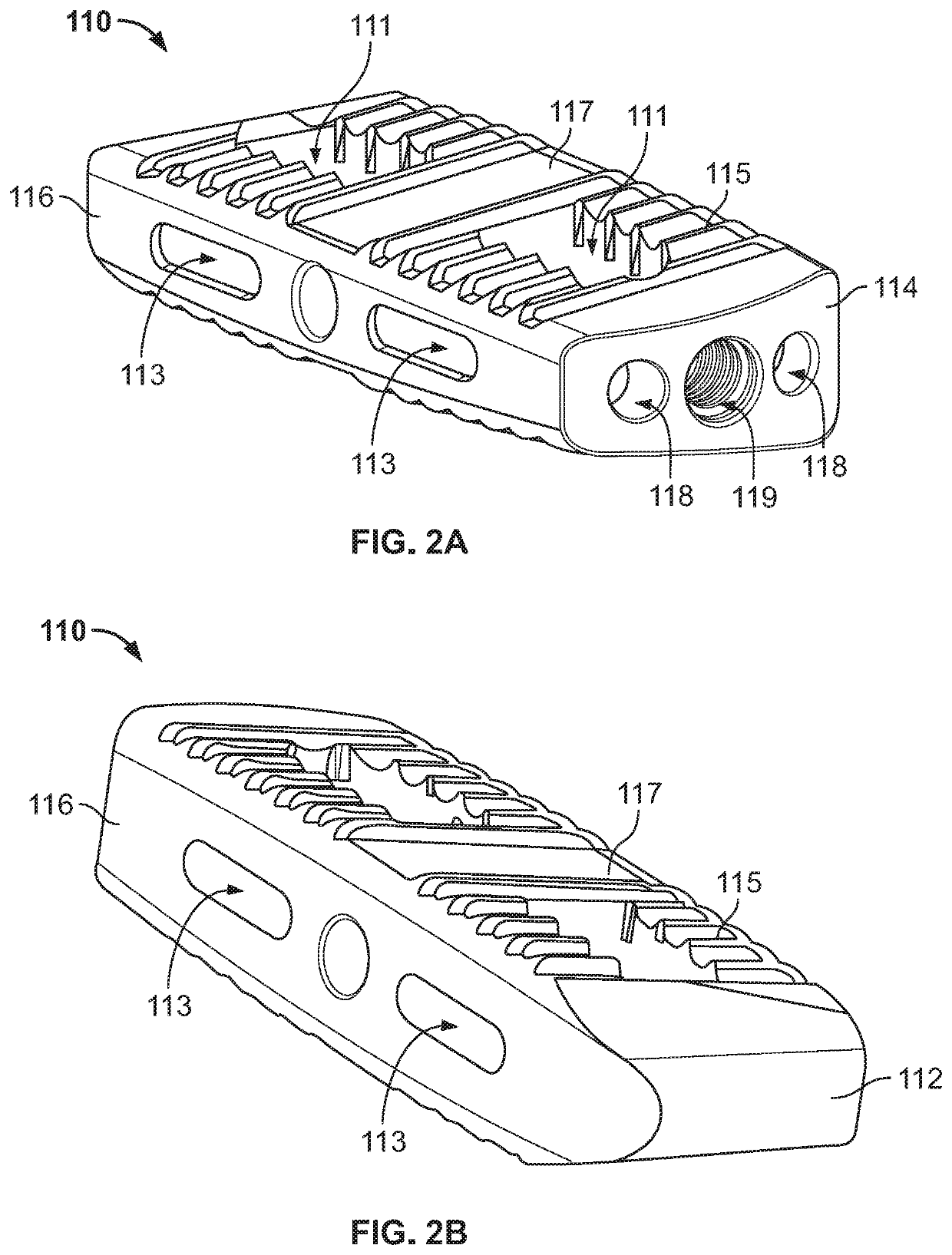
A spinal fusion system comprising an interbody device includes a leading end, trailing end, and opposed bone contacting sides extending therebetween. The trailing end defines a threaded opening that extends toward the leading end. The system also includes a bone plate that includes inner and outer surfaces and defines a first bone screw opening and connection screw opening extending therethrough. The system further includes a connection screw that includes a head and a threaded shaft. The head is positioned within the connection screw opening of the bone plate and is rotatably connected thereto such that the connection screw is rotatable about a longitudinal axis thereof but is prohibited from translational movement relative to the bone plate. The threaded shaft extends from the connection screw opening and is configured for threaded engagement with the threaded opening of interbody device.

Description

CROSS-REFERENCE TO RELATED APPLICATIONS[0001]This application claims the benefit of the filing date of U.S. Provisional Patent Application No. 62 / 813,251, filed Mar. 4, 2019, the disclosure of which is hereby incorporated herein by reference.BACKGROUND OF THE INVENTION[0002]The spine is comprised of a plurality vertebrae that are cushioned by intervertebral discs. Such intervertebral discs can deteriorate or become damaged due to injury, disease, or extended wear which may result in significant back pain that limits a patient's mobility and quality of life. One method of treatment that has been widely utilized is spinal fusion, whereby an affected disc is partially or fully excised and vertebral bodies adjacent such disc are fused together through the use of interbody devices, such as spacers, cages, and the like.[0003]The aforementioned devices are often packed with a bone growth promoting material, such as bone graft and / or any known combination of biologics. In addition, some int...

Claims


Application Information

Patent Timeline
IPC IPC(8): A61F2/44
CPCA61F2/442A61F2002/30205A61F2/447A61F2002/30578A61F2002/30433A61F2002/30785A61F2002/305A61F2002/30011A61F2/4611A61F2002/3079A61F2002/4627A61B17/8042A61F2002/30405A61F2002/30574
Inventor MILZ, BRYAN D.SOSNOV, ZINOVIYALHEIDT, THOMAS A.RYANGREENDYK, STEVEN
Owner K2M
Why Eureka
Try Eureka