Method and device for placing thin material layers onto a relief mould

a relief mould and material layer technology, applied in the field of layered materials, can solve the problems of large technical implementation expenditure, enormous cost, and inability to return anywhere near satisfactory, and the material layer that is to be placed into the relief mould does not fit in the tool mould

Inactive Publication Date: 2011-11-29
AIRBUS OPERATIONS GMBH +1
View PDF17 Cites 7 Cited by
  • Summary
  • Abstract
  • Description
  • Claims
  • Application Information

AI Technical Summary

Benefits of technology

[0009]A second embodiment of the method according to the invention for placing at least one material layer onto a relief mould for producing a composite material provides for an elastically-reversibly deformable surface to be arranged on the material layer such that the surface rests flat against the material layer. Thereby, there is no need for the surface to have a surface relief that corresponds to the relief mould. In order to, again, be able to pick up the material layer from its support on which it has been placed, a retention force is generated that fixes, at least temporarily, the material layer to the surface. Also in this embodiment of the method it is possible to generate the retention force already prior to arranging the surface on the material layer. After this the surface, together with the material layer fixed thereto, can be arranged facing the relief mould and subsequently, by the surface, the material layer can be pressed against the relief mould in such a way that the material layer is given a surface relief that corresponds to the relief mould. By this adaptation of the material layer by the elastically-reversibly deformable surface, it is again possible to ensure wrinkle-free placement of the material layer onto the relief mould. After a surface relief that corresponds to the relief shape has been forced onto the material layer in this way, finally the retention force can be cancelled in order to place and deposit the material layer onto the relief mould in this way.
[0011]With the two previously described methods it is thus very easy to remove material layers in an automated way from a flat surface and to place them, free of any wrinkles, with a defined surface structure onto a relief mould. The methods make it possible to place material layers of different sizes onto geometric relief shapes that are different or at least similar. With the use of the method according to the invention it is possible to do without expensive robot-gripper kinematics, as a result of which the costs incurred can be reduced and process reliability can be enhanced.
[0019]Since due to the elastically-reversible surface of the device according to the invention it is possible to pick up material layers of different sizes by the device, it is intended that, depending on the size of the material layer, a suction stream be applied only to those suction apertures that are covered by the material layer. If at all possible, no suction stream should be applied to the remaining exposed suction apertures as this would involve unnecessary loss of energy. In order to ensure this targeted application of a suction stream to designated suction apertures, the device comprises a multitude of suction chambers, wherein each one of the multitude of suction chambers is connected to a plurality of the multitude of tubes. In this way, by separate activation of the individual suction chambers, it can be ensured that a suction stream is applied in a targeted way to the suction apertures.

Problems solved by technology

While there have been experiments to automate the placing of material layers in the mould tool, these experiments have, however, so far exclusively resulted in very expensive robot-gripper kinematics that are associated with very considerable technical implementation expenditure and enormous costs without returning anywhere near satisfactory results.
Thus, such tool moulds for the production of layered materials as a rule comprise lateral delimitations, which results in a material layer that is to be placed into a mould not fitting in the tool mould in the stretched state of said material layer.
Furthermore, when placing material layers in a tool mould there is a further problem in that in order to produce particular geometric shapes of the composite to be produced, several material layers of different sizes are placed in a tool mould, for example in order to achieve material reinforcement in one position of the composite.

Method used


Image

  • Method and device for placing thin material layers onto a relief mould
  • Method and device for placing thin material layers onto a relief mould
  • Method and device for placing thin material layers onto a relief mould

Examples


Embodiment Construction

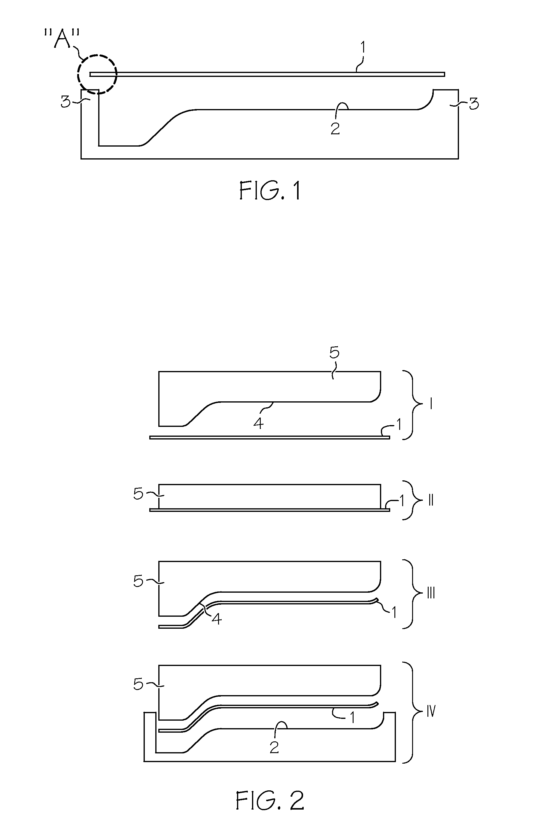
[0026]Below, with reference to FIG. 1, the problem is explained that can be encountered when placing a material layer in a relief mould. FIG. 1 shows a relief mould 2 that is laterally delimited by two sidewalls 3. Since the surface of the relief mould 2 comprises a height gap, the material layer 1 that is to be deposited to the relief mould 2 must be of a length that corresponds to the unwinding of the relief mould 2. This makes it necessary for the length of the material layer 1 to be longer than the clearance between the two sidewalls 3, which is why the material layer 1, as indicated in FIG. 1 by the region “A”, overlaps the left sidewall 3 so that in this way it cannot be placed flat onto the relief mould 2.

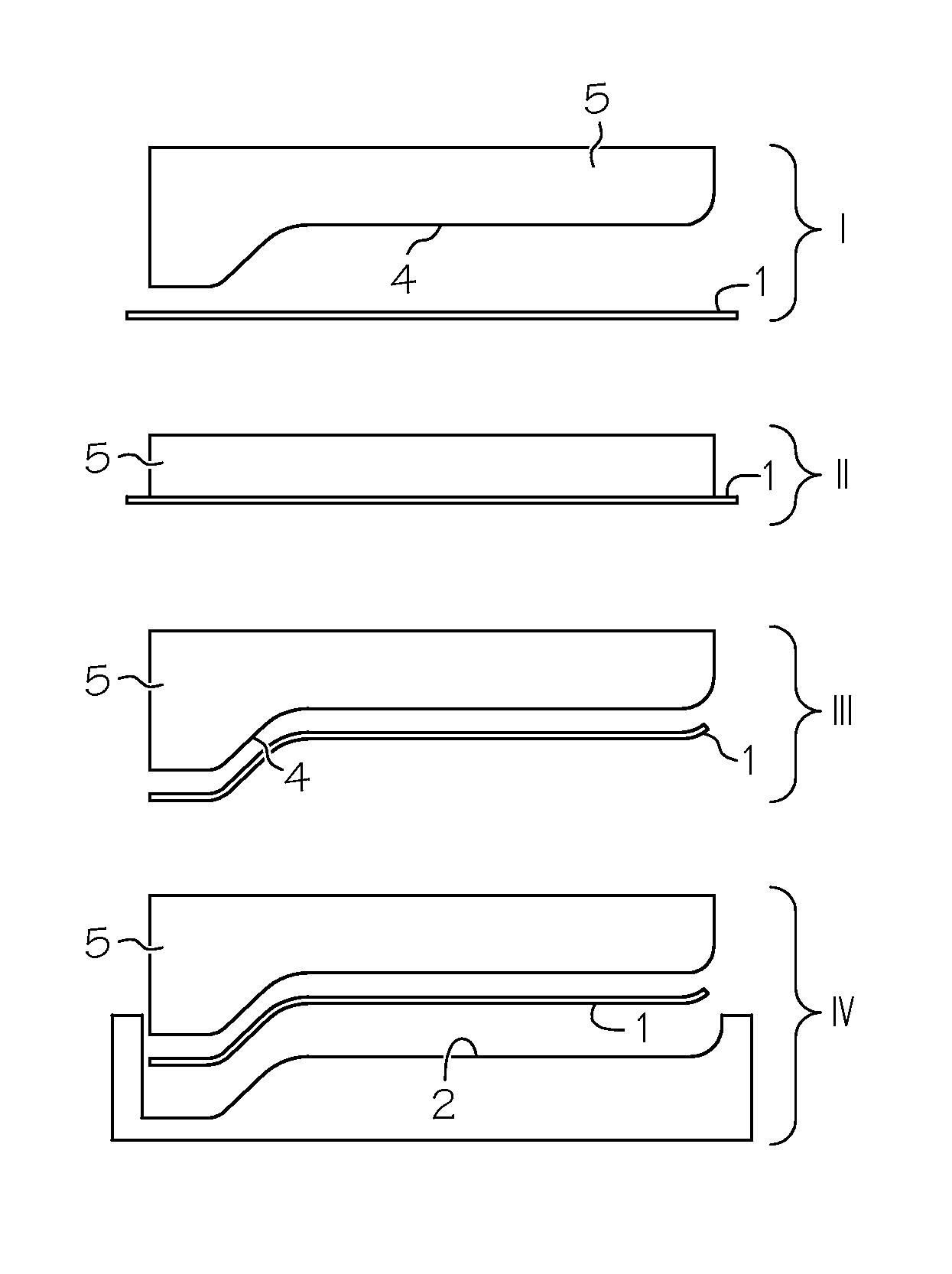
[0027]In order to solve this problem, as well as solving the additional problems, as mentioned above, encountered during the placement of a material layer 1 in a relief mould 2, the present invention therefore proposes two differently designed methods, of which a first metho...


PUM

PropertyMeasurementUnit
pressure forceaaaaaaaaaa
retention forceaaaaaaaaaa
surface reliefaaaaaaaaaa

Abstract

The present invention relates to a method and a device for placing at least one material layer onto a relief mold for producing a composite material. Thereby, an elastically-reversibly deformable body with a surface relief that is designed to correspond to the relief mold is pressed against the material layer, as a result of which the surface of said body is deformed, and the material layer can be picked up. As a result of its elastically-reversible characteristics the body subsequently deforms back to its initial state so that the material layer can easily be placed onto the relief mold.

Description

CROSS-REFERENCE TO RELATED APPLICATIONS[0001]This application is a U.S. National-Stage entry under 35 U.S.C. §371 based on International Application No. PCT / EP2006 / 009065, filed Sep. 18, 2006, which was published under PCT Article 21(2) and which claims priority to German Patent Application No. 10 2005 044 823.2 filed Sep. 20, 2005 and U.S. Provisional Patent Application No. 60 / 718,652 filed Sep. 20, 2005, the disclosures of which are hereby incorporated herein by reference.TECHNICAL FIELD[0002]The present invention, generally speaking, relates to the technical field of producing layered materials. In particular, the invention relates to two different methods for placing at least one material layer onto a relief mould for producing a composite material. Furthermore, the invention relates to a device for placing at least one material layer onto a relief mould for producing a composite material. Finally, the invention relates to the use of such a device in order to place, with it, at ...

Claims


Application Information

Patent Timeline
Patent Type & Authority Patents(United States)
IPC IPC(8): B28B7/30
CPCB29C31/008B29C70/386B29C70/541B32B38/18B32B38/1858B32B2038/1891
Inventor EBERTH, ULRICHKRAFFT, HANS-MARTINFRIEDRICH, MARTIN
Owner AIRBUS OPERATIONS GMBH
Why Eureka
Try Eureka