Central electricity distribution member for rotary electric machine

a technology of rotary electric machines and distribution members, which is applied in the direction of windings, dynamo-electric components, supports/enclosements/casings, etc., can solve the problems of poor assembly matching and structur

Active Publication Date: 2011-11-29
TOYOTA JIDOSHA KK +1
View PDF14 Cites 2 Cited by
  • Summary
  • Abstract
  • Description
  • Claims
  • Application Information

AI Technical Summary

Benefits of technology

[0012]According to at least one of the above-described structures, the central electricity distribution member for a rotary electric machine comprises an insulation-side positioning portion provided on the bus bar insulating portion and a bus bar-side positioning portion provided on each of the bus bars for performing positioning between the bus bar insulating portion and the respective bus bars in cooperation with the insulation-side positioning portion. Therefore, positioning can be attained between the respective bus bars and bus bar insulating portion.
[0013]According to at least one of the above-described structures, in the central electricity distribution member for a rotary electric machine, the insulation side positioning portion is one of the inside walls opposed to the groove width direction of the holding groove, the one inside wall having at least a part thereof inclined such that the groove width of the holding groove becomes smaller from the opening side to the bottom surface side of the holding groove, and the bus bar-side positioning portion is a convex portion for abutting on the inclined wall. Therefore, positioning can be attained in the groove width direction of the holding groove between the respective bus bars and the bus bar insulating portion.
[0014]According to at least one of the above-described structures, the insulation side positioning portion is a convex portion which once protrudes on the bottom surface of the holding grove along the longitudinal direction of the holding groove and then returns to its original level, and the bus bar-side positioning portion is a concave portion for accepting the convex portion of the holding groove, the convex portion being formed on the bottom surface of the holding groove. Therefore, positioning can be attained in the longitudinal direction of the holding groove between the respective bus bars and bus bar insulating portion.
[0015]According to at least one of the above-described structures, the central electricity distribution member for a rotary electric machine further comprises a pressing cover portion for pressing the respective bus bars in the depth direction of the holding groove, wherein the bus bar insulating portion has an insulation-side engagement portion formed on at least one of the outside walls on the radially inward and outward sides, and the pressing cover portion has a cover-side engagement portion for causing the pressing cover portion to be engaged with the bus bar insulating portion in cooperation with the insulation-side engagement portion. Therefore, positioning can be attained in the depth direction of the holding groove between the respective bus bars and the bus bar insulating portion.

Problems solved by technology

However, although the structure of the Patent Document 1 can realize insulation among the bus bars of the respective phases, the structure may suffer from poor matching in assembly due to lack of position regulation for the respective bus bars and bus bar insulating portion, or an insulating holder.

Method used


Image

  • Central electricity distribution member for rotary electric machine
  • Central electricity distribution member for rotary electric machine
  • Central electricity distribution member for rotary electric machine

Examples


Embodiment Construction

[0021]In the following, an embodiment of the present invention will be described in detail with reference to the accompanying drawings. Note that although a concentrated winding will be described as a method for winding a coil of a rotary electric machine, a distributed winding will be similarly applicable.

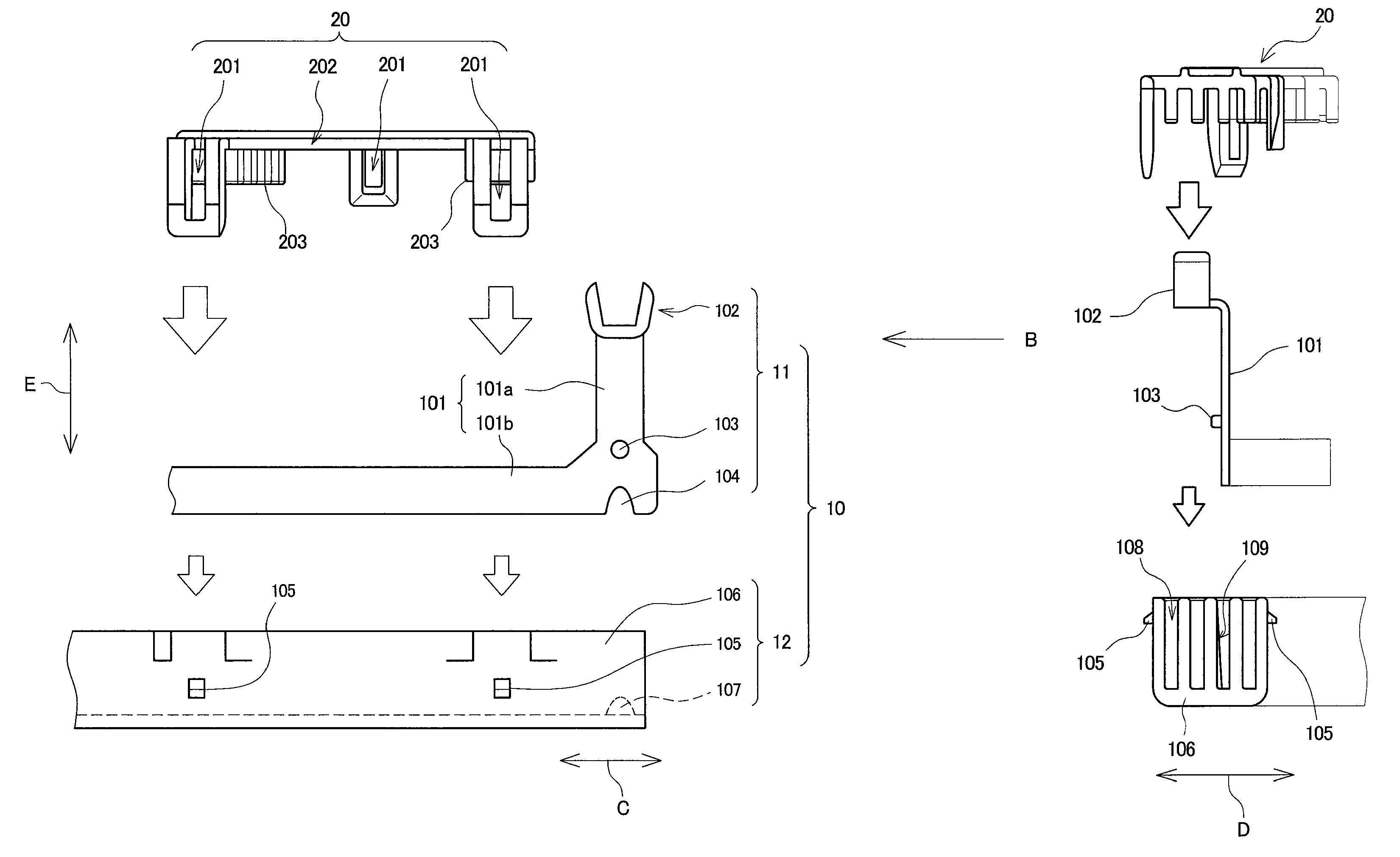
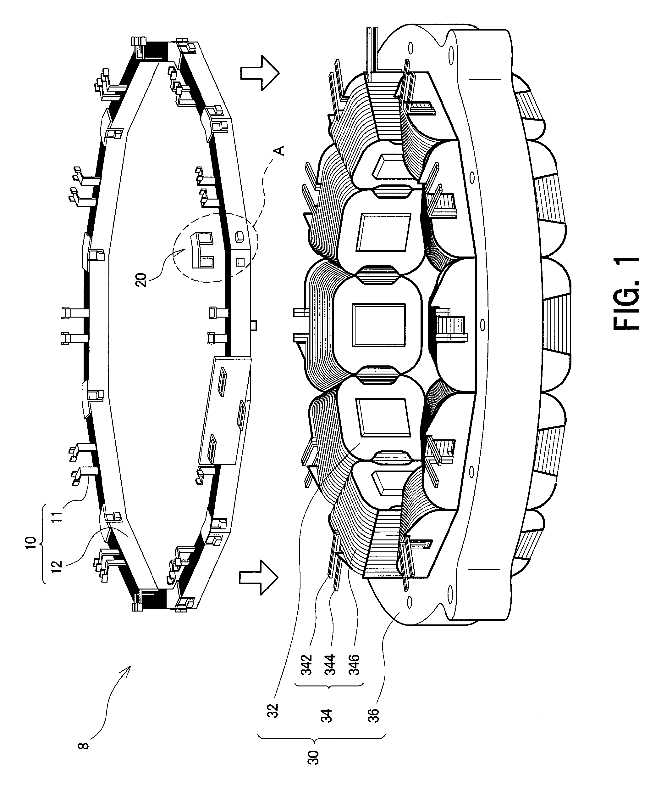
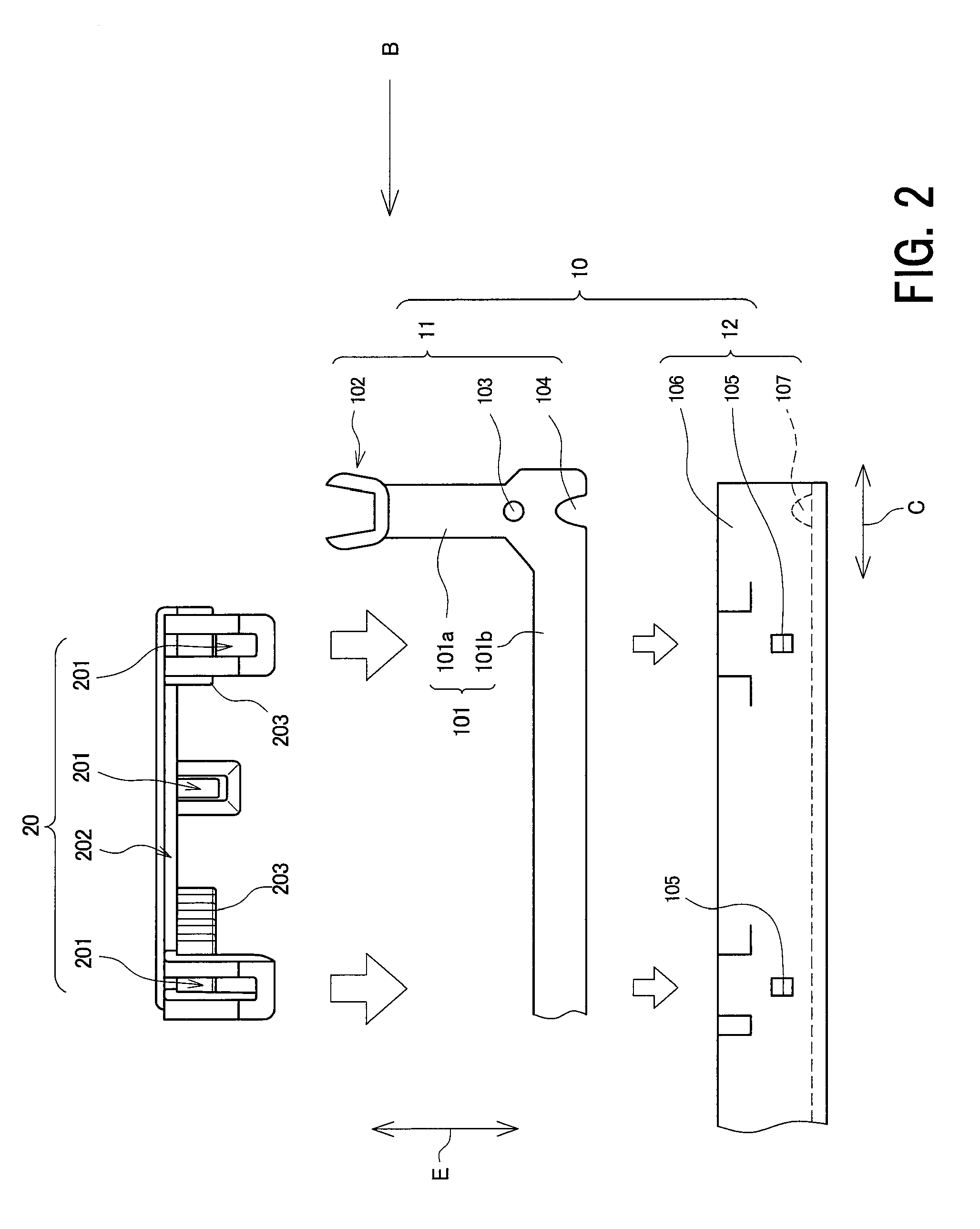
[0022]FIG. 1 is a diagram showing a state in which a central electricity distribution member 8 is mounted on a stator 30 of a rotary electric machine. FIG. 2 is an enlarged view showing a portion enclosed by the broken line A in FIG. 1, specifically showing a connecting bus bar 11, a bus bar insulating portion 12, and a central electricity distribution member cover portion 20 in such a manner that these are separated from one another. FIG. 3 is a diagram corresponding to FIG. 2, as viewed from the direction indicated by arrow B.

[0023]The stator 30 comprises a stator yoke 36, teeth 32 extending from the stator yoke 36 in the radially inward direction, and a coil 34 wound around eac...


PUM


Abstract

A central electricity distribution member for a rotary electric machine, comprising connecting bus bars of respective phases for connecting, among coils of respective phases wound around a stator of the rotary electric machine, the coils of the same phases; a connecting bus bar for a neutral point for connecting the coils of the same phases wound around the stator of the rotary electric machine; a circular holding groove capable of receiving the respective connecting bus bars as the respective connection bus bars are insulated from one another; a bus bar insulating portion formed using insulating material; a bus bar-side positioning portion provided on each of the connecting bus bars; and an insulation-side positioning portion provided on the bus bar insulating portion, for performing positioning between the respective connecting bus bars and the bus bar insulating portion in cooperation with the bus bar-side positioning portion.

Description

PRIORITY INFORMATION[0001]This application claims priority to Japanese Patent Application No. 2007-320637 filed on Dec. 12, 2007, which is incorporated herein by reference in its entirety.BACKGROUND OF THE INVENTION[0002]1. Field of the Invention[0003]The present invention relates to a central electricity distribution member for a rotary electric machine, and in particular to a central electricity distribution member for a rotary electric machine having bus bars of respective phases.[0004]2. Description of the Related Art[0005]A rotary electric machine having bus bars of respective phases requires insulation among the respective bus bars. For example, Patent Document 1 describes a central electricity distribution member having a plurality of bus bars corresponding to respective phases of a motor, and a continuous circular plastic insulating holder, in which three holding grooves are formed on one side surface of the insulating holder so as to be recessed and to extend along the circ...

Claims


Application Information

Patent Timeline
Patent Type & Authority Patents(United States)
IPC IPC(8): H02K11/00
CPCH02K3/522H02K5/225H02K2203/09
Inventor SASAKI, KEIOKAMOTO, MASAKI
Owner TOYOTA JIDOSHA KK
Why Eureka
Try Eureka