
Drug inspection assistance device, drug identification device, image processing device, image processing method, and program

a technology for drug identification and assistance devices, which is applied in the direction of image enhancement, pharmaceutical product form changes, instruments, etc., can solve the problems that the information other than that on the engraved mark cannot be reduced, and the collation with the master image cannot be appropriately performed, so as to reduce the information, and enhance the engraved mark or printed character portions.

Active Publication Date: 2021-12-07
FUJIFILM TOYAMA CHEMICAL CO LTD
View PDF16 Cites 0 Cited by
  • Summary
  • Abstract
  • Description
  • Claims
  • Application Information

AI Technical Summary

Benefits of technology

[0010]The present invention has been made in view of such situations, and has an object to provide a drug inspection assistance device, a drug identification device, an image processing device, an image processing method, and a program that can reduce information such as a pattern, a scar and the like on a surface of a drug which are other than an engraved mark and are smaller than a width of a groove of the engraved mark, and accurately extract the engraved mark.
[0027]According to the present invention, it is possible to reduce the information such as a pattern, a scar and the like on a surface of a drug which are other than that on the engraved mark and are smaller than the width of the groove of the engraved mark, and extract the engraved mark.

Problems solved by technology

However, the device in PTL 1 cannot reduce the information other than that on the engraved mark.
If information other than that on the engraved mark, such as the patchy pattern, is obtained in this manner, there is a problem that collation with the master image cannot be appropriately performed.

Method used


Image

  • Drug inspection assistance device, drug identification device, image processing device, image processing method, and program
  • Drug inspection assistance device, drug identification device, image processing device, image processing method, and program
  • Drug inspection assistance device, drug identification device, image processing device, image processing method, and program

Examples


first embodiment

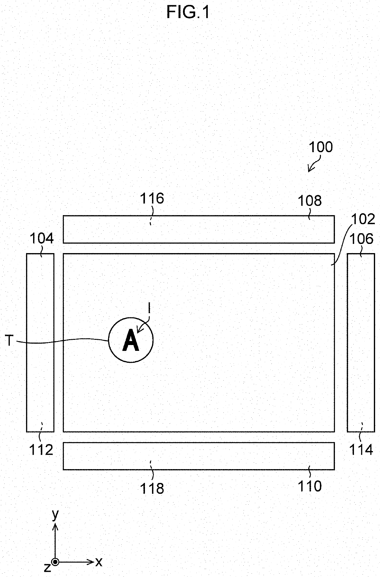
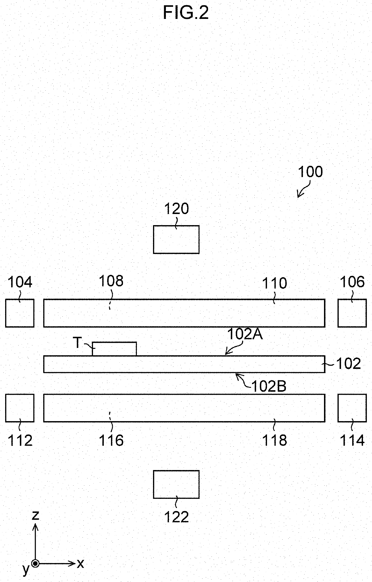
[0068]FIG. 1 is a top view of a drug identification device 100 (an example of an image processing device) according to the FIG. 2 is a side view of the drug identification device 100.

[0069]As shown in FIGS. 1 and 2, the drug identification device 100 includes a stage 102, a first light source 104, a second light source 106, a third light source 108, a fourth light source 110, a fifth light source 112, a sixth light source 114, a seventh light source 116, an eighth light source 118, a camera 120, and a camera 122. Note that in FIG. 1, illustration of the camera 120 and the camera 122 is omitted.

[0070]The stage 102 is a plate-shaped member that has a mounting surface 102A and a rear surface 102B, which are parallel to the xy plane (horizontal plane). The stage 102 is made of a material having light transparency. Here, the stage 102 has sizes of 130 mm in the x-axis direction, and 80 mm in the y-axis direction. A tablet T (an example of a drug) is placed on the mounting surface 102A o...

second embodiment

[0114]FIG. 7 is a perspective view of a drug identification device 140 according to a FIG. 8 is a top view of the drug identification device 140. Note that the parts common to those of the drug identification device 100 shown in FIGS. 1 and 2 are assigned the same numerals or characters; their detailed description is omitted.

[0115]As shown in FIGS. 7 and 8, the drug identification device 140 includes a stage 102, a camera 120, a camera 122, a mounting-surface-side dome lamp 142, and a rear-surface-side dome lamp 148. Note that in FIG. 8, illustration of the camera 120, the camera 122 and the rear-surface-side dome lamp 148 is omitted.

[0116]The mounting-surface-side dome lamp 142 is supported by a supporting unit, not shown, at a position apart by a certain amount from the stage 102 on one side (on a mounting surface 102A side) in the z-axis direction. The mounting-surface-side dome lamp 142 is configured to include a light source supporting unit 144 and a plurality of point light s...

third embodiment

[0139]FIG. 9 is a top view of a drug identification device 160 according to a FIG. 10 is a side view of the drug identification device 160. Note that the parts common to those of the drug identification device 100 shown in FIGS. 1 and 2 are assigned the same numerals or characters, and their detailed description is omitted.

[0140]As shown in FIGS. 9 and 10, the drug identification device 160 includes a stage 102, a first light source 104, a fifth light source 112, a camera 120, a camera 122, a first epi-illumination lamp 162, and a second epi-illumination lamp 168. Note that in FIG. 9, illustration of the camera 120, the camera 122 and the second epi-illumination lamp 168 is omitted.

[0141]The first epi-illumination lamp 162 is disposed on the optical axis of the camera 120 between the stage 102 and the camera 120 and is supported by a supporting unit, not shown. The first epi-illumination lamp 162 includes a light source 164 and a half mirror 166.

[0142]An LED light source is used fo...


PUM


Abstract

A image processing device which can reduce information such as a pattern, a scar and the like on a surface of a drug which are other than an engraved mark, to accurately extract the engraved mark. The image processing device includes: an obtaining unit configured to obtain a plurality of images of a drug having an engraved mark on a surface of the drug, with emitting directions of light to the surface different from each other; an edge image generating unit configured to apply respectively to the plurality of images, edge extracting filters in directions in conformity with the emitting directions, the edge extracting filters having a size in conformity with a width of a groove of the engraved mark, and generate a plurality of edge images; and an image composing unit configured to compose the plurality of edge images and generate a composite image.

Description

CROSS-REFERENCE TO RELATED APPLICATIONS[0001]The present application is a Continuation of PCT International Application No. PCT / JP2018 / 029925 filed on Aug. 9, 2018 claiming priority under 35 U.S.C § 119(a) to Japanese Patent Application No. 2017-159559 filed on Aug. 22, 2017. Each of the above applications is hereby expressly incorporated by reference, in its entirety, into the present application.BACKGROUND OF THE INVENTION[0002]1. Field of the Invention[0003]The present invention relates to a drug inspection assistance device, a drug identification device, an image processing device, an image processing method, and a program, and in particular, to a drug inspection assistance device, a drug identification device, an image processing device, an image processing method, and a program that read an engraved mark applied to a drug.[0004]2. Description of the Related Art[0005]There are known devices that identify a kind of a drug from a taken image obtained by imaging the drug. For exam...

Claims


Application Information

Patent Timeline
Patent Type & Authority Patents(United States)
IPC IPC(8): G06K9/44G06T7/13G16H70/40A61J3/00G06K9/46G06V10/141
CPCG06K9/44A61J3/007G06K9/4604G06T7/13G16H70/40G06T2207/20221G06T5/50G16H20/10G16H30/40G16H40/20G06T2207/10152G06V20/64G06V10/141G06V10/443G06V20/66
Inventor IWAMI, KAZUCHIKA
Owner FUJIFILM TOYAMA CHEMICAL CO LTD
Learn More