Molded Surface Fastener, Cushion Body, Cushion Body Manufacturing Method, and Molding Die

a cushion body and molding die technology, applied in haberdashery, transportation and packaging, vehicle arrangements, etc., can solve the problems of cushion body looseness, lower quality of an outside appearance of a product depending on the product, and loose skin material attached to the cushion body. achieve the effect of easy operation

Active Publication Date: 2017-02-16
YKK CORP +1
View PDF1 Cites 2 Cited by
  • Summary
  • Abstract
  • Description
  • Claims
  • Application Information

AI Technical Summary

Benefits of technology

[0052]The molded surface fastener according to the invention includes at least one surface fastener portion in which an engaging region is formed of a plurality of hook-shaped engaging elements standing on a flat plate-shaped substrate portion and a foldable piece portion extending from one end edge portion in a width direction of the surface fastener portion and at least a part thereof has flexibility.
[0053]Further, the surface fastener portion includes a pair of first barrier portions standing along a width direction at both end portions in a length direction of the substrate portion between which the engaging region is disposed, and preventing a foam resin material from penetrating into the engaging region from a length direction at the time of foam molding of the cushion body, and a second barrier portion standing along a length direction on a first surface on an end edge portion on an opposite side of the foldable piece portion of the substrate portion, and preventing the foam resin material from penetrating into the engaging region from a width direction at the time of foam molding.
[0054]According to the molded surface fastener of the present invention, when the cushion body is foamed and molded using a molding die, foam molding of the cushion body can be performed while the foldable piece portion of the molded surface fastener is held at the first holding portion of the fastener holding portion provided on the molding die in a state that the foldable piece portion of the molded surface fastener is folded with respect to the surface fastener portion, and the first and the second barrier portions of the surface fastener portion of the molded surface fastener are closely contacted to the second holding portions of the fastener holding portion.
[0055]The foldable piece portion can be used as a positioning portion by holding the surface fastener portion and the foldable piece portion at the fastener holding portion of the molding die in a state that both are folded at the time of foam molding of the cushion body. Therefore, a positioning operation of the molded surface fastener can be performed easily without using an exclusive support member, as mentioned in Patent Document 4, for example, and the molded surface fastener can be held at a predetermined position with respect
[0056]When the molded surface fastener is held at the fastener holding portion of the molding die, the first and the second barrier portions of the surface fastener portion are closely contacted with the second holding portions of the fastener holding portion, as mentioned above. Therefore, the foam resin material can be prevented from penetrating into the engaging region beyond the first and the second barrier portions of the molded surface fastener at the time of foam molding of the cushion body.
[0057]Accordingly, the molded surface fastener can be held at a predetermined position with respect to the molding die, and the foam resin material can be prevented from penetrating into the engaging region by holding the molded surface fastener of the present invention at the fastener holding portion of the molding die and performing foam molding of the cushion body using the foldable piece portion as a positioning portion. In this case, a groove portion for fixing a skin material having a small groove width is formed by the fastener holding portion of the molding die on the cushion body which is foamed and molded, and the molded surface fastener of the present invention can be stably placed at a predetermined position with respect to the groove portion for fixing a skin material of the cushion body. Further, even after the foam molding of the cushion body, the engaging region of the molded surface fastener can be exposed in the groove portion for fixing the skin material without being buried in the cushion body, which can secure a desired stable engagement force of the engaging elements.

Problems solved by technology

However, a large groove width of the groove portion provided on the surface of the cushion body may cause a looseness of the skin material attached to the cushion body.
Further, the engaging portion of the skin material for engaging with the molded surface fastener of the cushion body may appear to recess in a strip-shape, which lowers quality of an outside appearance of a product depending on the product to which the cushion body is used.

Method used


Image

  • Molded Surface Fastener, Cushion Body, Cushion Body Manufacturing Method, and Molding Die
  • Molded Surface Fastener, Cushion Body, Cushion Body Manufacturing Method, and Molding Die
  • Molded Surface Fastener, Cushion Body, Cushion Body Manufacturing Method, and Molding Die

Examples


embodiment 1

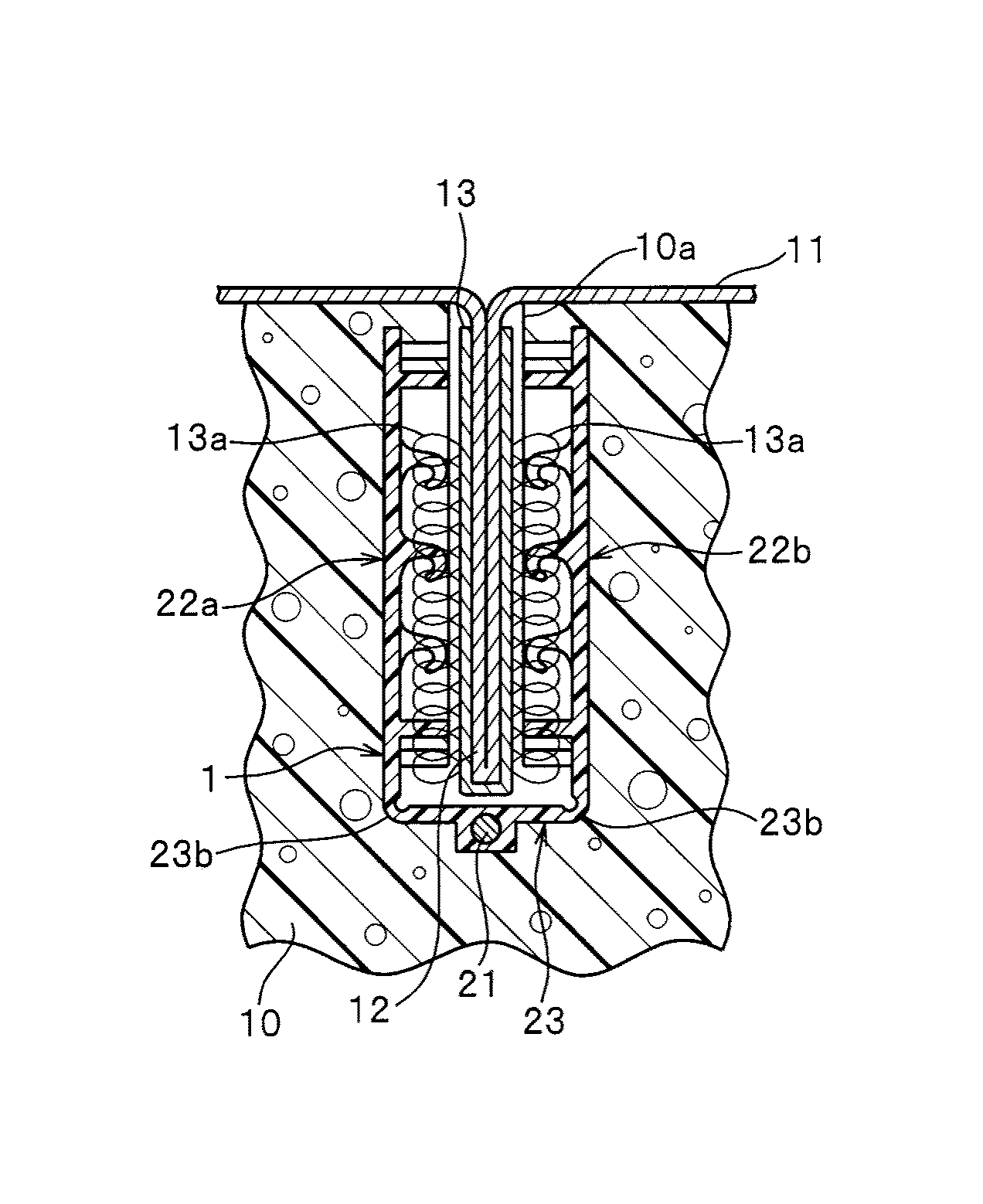
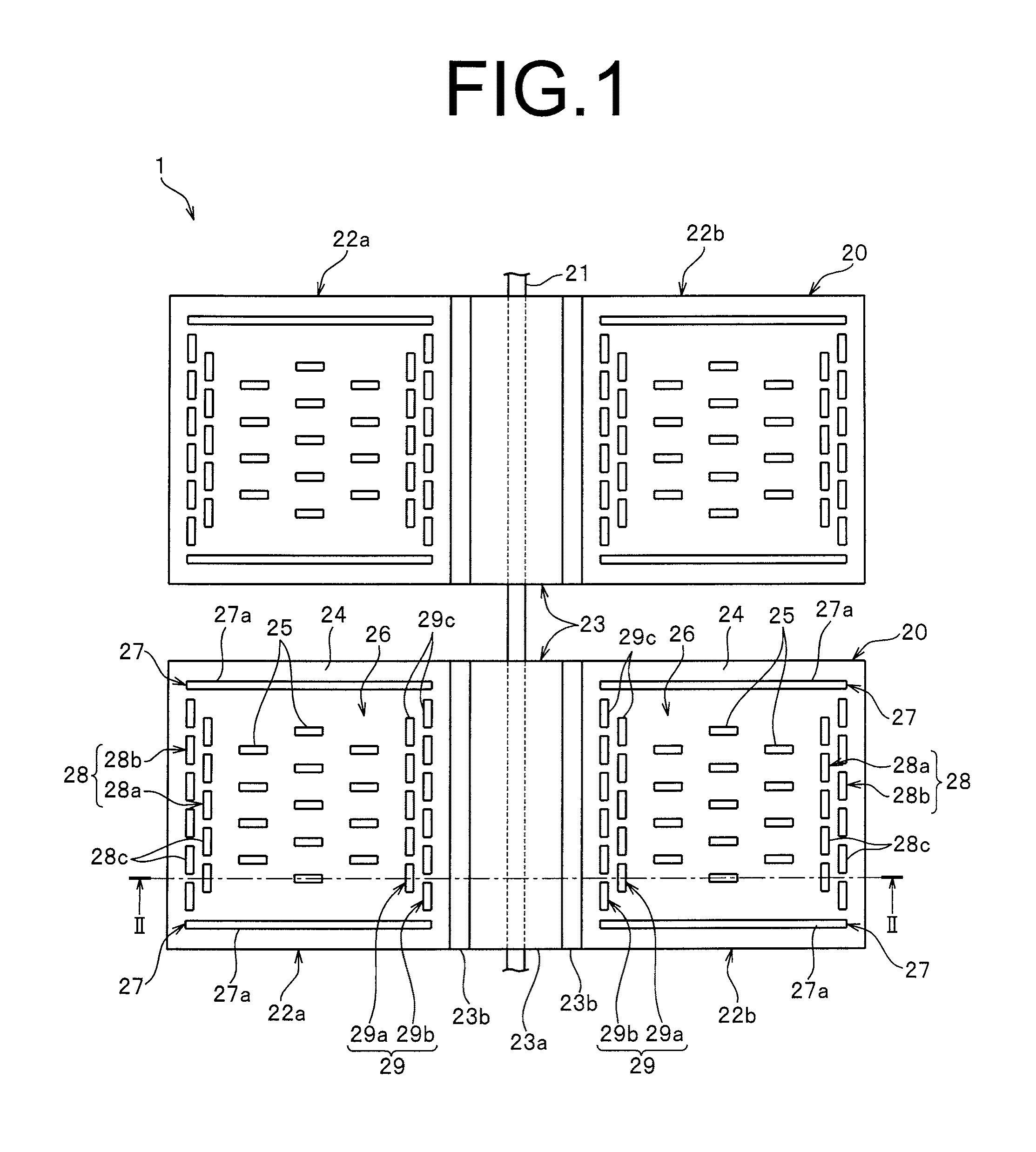
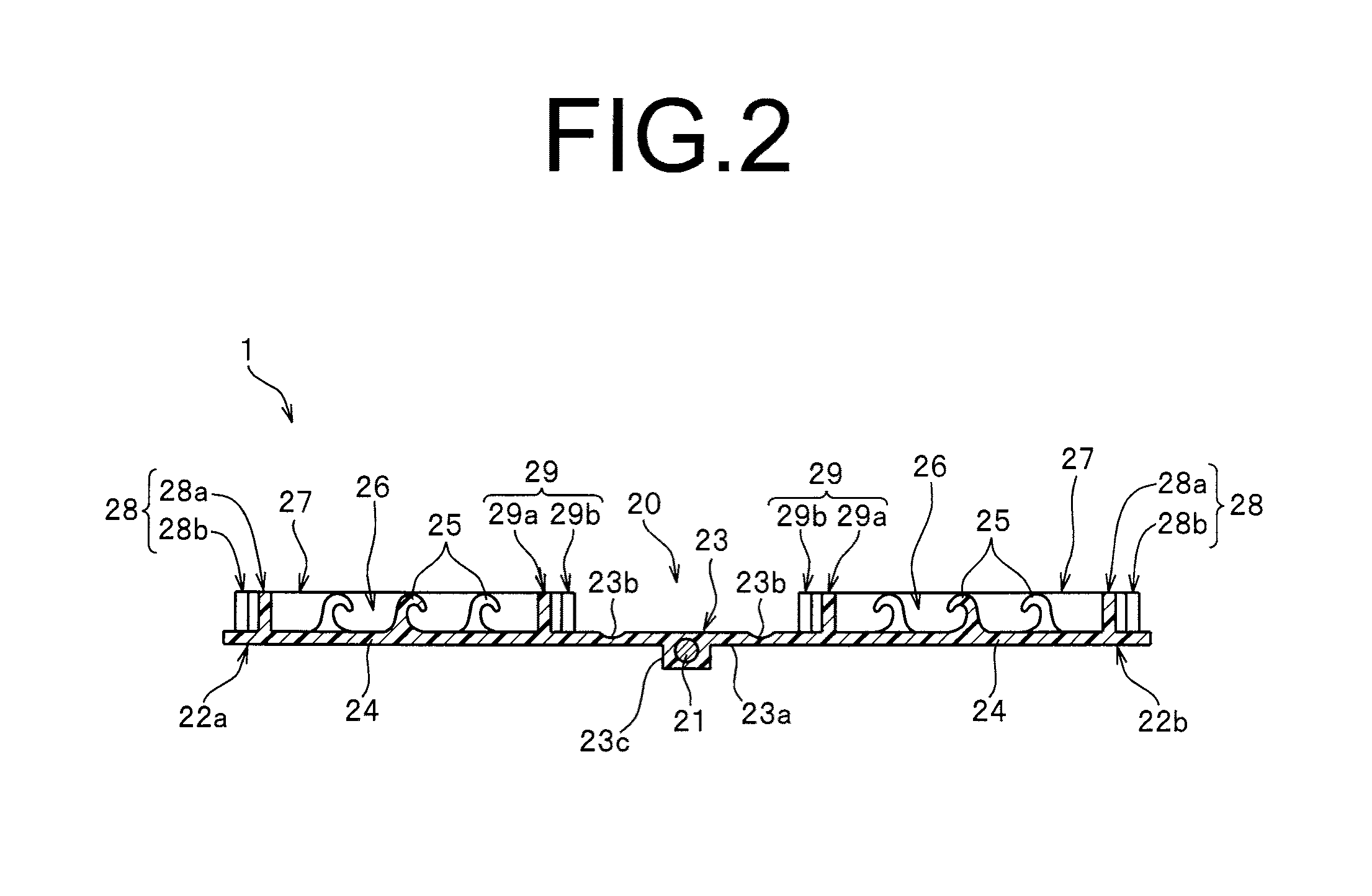
[0115]FIG. 1 is a plan view illustrating a molded surface fastener according to Embodiment 1, and FIG. 2 is a cross-sectional view along the line II-II in FIG. 1.

[0116]In the following descriptions, a length direction or a front and rear direction regarding a molded surface fastener is defined as a same direction as a length direction of a groove portion for fixing a skin material formed on a surface of a cushion body to which the molded surface fastener is integrated. That is, when seeing FIG. 1, a direction of upside in FIG. 1 is referred to as “frontward”, and an opposite direction is referred to as “rearward”. The length direction of the groove portion for fixing a skin material means a direction perpendicular to a groove width direction and a groove depth direction of the groove portion for fixing a skin material.

[0117]A width direction or a left and right direction regarding the molded surface fastener means a direction perpendicular to the length direction or the front-rear d...

embodiment 2

[0212]FIG. 11 shows a schematic view illustrating a state the molded surface fastener of Embodiment 2 is attached to the fastener holding portion of the molding die.

[0213]Please note that regarding the molded surface fastener of Embodiment 2 as mentioned below and the molded surface fasteners of Embodiments 3 to 9 described later, structural features different from the molded surface fastener of Embodiment 1 will be mainly described, and parts and members having substantially same as those of the molded surface fastener of Embodiment 1 will not be described but represented by the same reference numerals.

[0214]The molded surface fastener 2 according to Embodiment 2 has a plurality of surface fastener members 20 disposed along the length direction and a connecting member 21 fixed to respective surface fastener members 20.

[0215]Each surface fastener member 20 has a pair of left and right, first and second surface fastener portions 22a, 22b and a foldable piece portion 23 disposed betwe...

embodiment 3

[0235]FIG. 13 shows a plan view illustrating a molded surface fastener according to Embodiment 3. FIG. 14 shows a perspective view illustrating a state that the molded surface fastener is held at a fastener holding portion of a molding die.

[0236]The molded surface fastener 3 according to Embodiment 3 is manufactured by molding a material in which magnetic particles are mixed in thermoplastic resin using a die wheel, and has a plurality of surface fastener members 30 disposed along a length direction and a connecting portion 31a formed integrally with the surface fastener members 30 and connecting respective surface fastener members 30. Each surface fastener member 30 has a pair of left and right first and second surface fastener portions 22a, 22b and a foldable piece portion 33 disposed between the pair of the first and the second surface fastener portions 22a, 22b.

[0237]The first and the second surface fastener portions 22a, 22b of Embodiment 3 are constituted similar to the first...


PUM

PropertyMeasurementUnit
lengthaaaaaaaaaa
widthaaaaaaaaaa
flexibilityaaaaaaaaaa

Abstract

A molded surface fastener comprises at least one surface fastener portion and a foldable piece portion that extends from the surface fastener portion. At least a part of the foldable piece portion has flexibility. The surface fastener portion has a pair of first barrier portions and a second barrier portion. A cushion body with the molded surface fastener anchored to a prescribed position while a plurality of engaging elements are in an exposed state can be stably manufactured by way of foam molding the cushion body using the molded surface fastener.

Description

TECHNICAL FIELD[0001]The present invention relates to a molded surface fastener that is integrated in a groove on a cushion body when the cushion body is foamed and molded, the cushion body to which the surface fastener is integrated, a method for manufacturing the cushion body and a molding die used to mold the cushion body.BACKGROUND ART[0002]Passenger seats of automobiles or trains, various kinds of sofas, office chairs, and the like are often formed by attaching a skin material such as fiber fabric or natural or synthetic leather to the surface of a cushion body (foaming body) molded in a predetermined shape by using a foam resin material. The cushion body used in these various seats often has a curved surface composed of convex-concave shapes satisfying human engineering factors in order to maintain a seating posture which provides no fatigue despite long-hour seating.[0003]Moreover, when a skin material is attached to the surface of a cushion body, after molding the cushion bo...

Claims


Application Information

Patent Timeline
Patent Type & Authority Applications(United States)
IPC IPC(8): A44B18/00B60N2/70B60N2/58
CPCA44B18/0076B60N2/5825A44B18/0049B60N2/7017A44B18/008B60N2/5891A44B18/0061A44B18/0019A44B18/0069B29C43/222B60N2/5833
Inventor MURASAKI, RYUICHIYAMAMOTO, TORUIYODA, YOSHITOMOMATSUMURA, GENTA
Owner YKK CORP
Why Eureka
Try Eureka