Installation for cryogenic cooling for superconductor device

a superconductor and installation technology, applied in the direction of superconducting magnets/coils, applications, lighting and heating apparatus, etc., can solve the problems of cryogenic fluid in liquid state, large and rapid increase in thermal load, and rapid and complete disappearan

Inactive Publication Date: 2011-12-06
EUROPEAN ORGANIZATION FOR NUCLEAR RESEARCH
View PDF12 Cites 0 Cited by
  • Summary
  • Abstract
  • Description
  • Claims
  • Application Information

AI Technical Summary

Benefits of technology

[0011]The object of the invention is essentially to propose an improved arrangement for an installation of the type in question, which allows it to operate correctly and reliably under standard thermal conditions but which, under abnormal thermal conditions, allows the device to be reimmersed more rapidly and its superconductivity state recovered more rapidly, and also prevents the loss of liquid cryogenic fluid initially present in the tank, therefore permitting a substantial saving of cryogenic fluid.
[0021]In order for the auxiliary tank to be able to be produced in a relatively compact form, it is advantageous for it to be placed substantially higher than the main tank that, furthermore, only a small amount of liquid cryogenic fluid is contained therein under normal thermal conditions.

Problems solved by technology

However, in the presence of a resistive transition of the device or of any other thermal disturbance resulting in a large and rapid increase in the thermal load, the cryogenic fluid in the liquid state, in contact with which the device must be maintained, rapidly and completely disappears owing to its vaporization, due to the increase in thermal load, and owing to its turbulent entrainment at high flow rate in the outlet manifold.
This new supply of liquid cryogenic fluid not only requires time, but above all requires an influx of fluid, which proves to be expensive.

Method used


Image

  • Installation for cryogenic cooling for superconductor device
  • Installation for cryogenic cooling for superconductor device
  • Installation for cryogenic cooling for superconductor device

Examples


Embodiment Construction

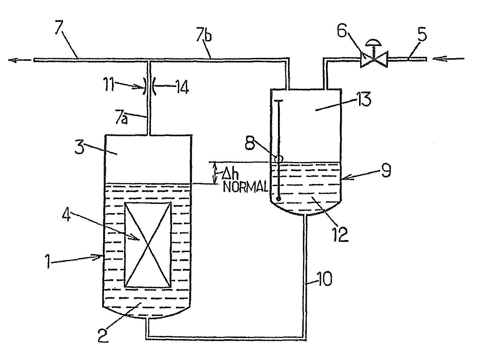
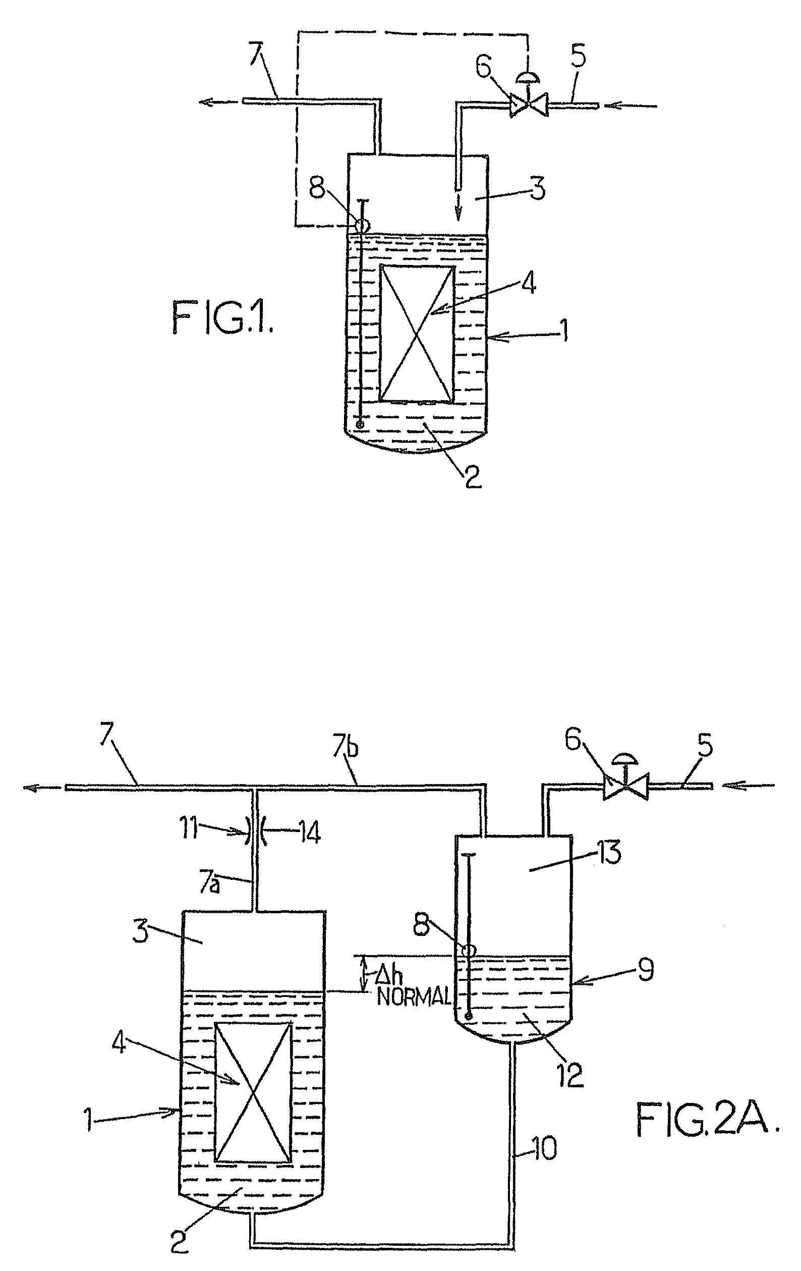
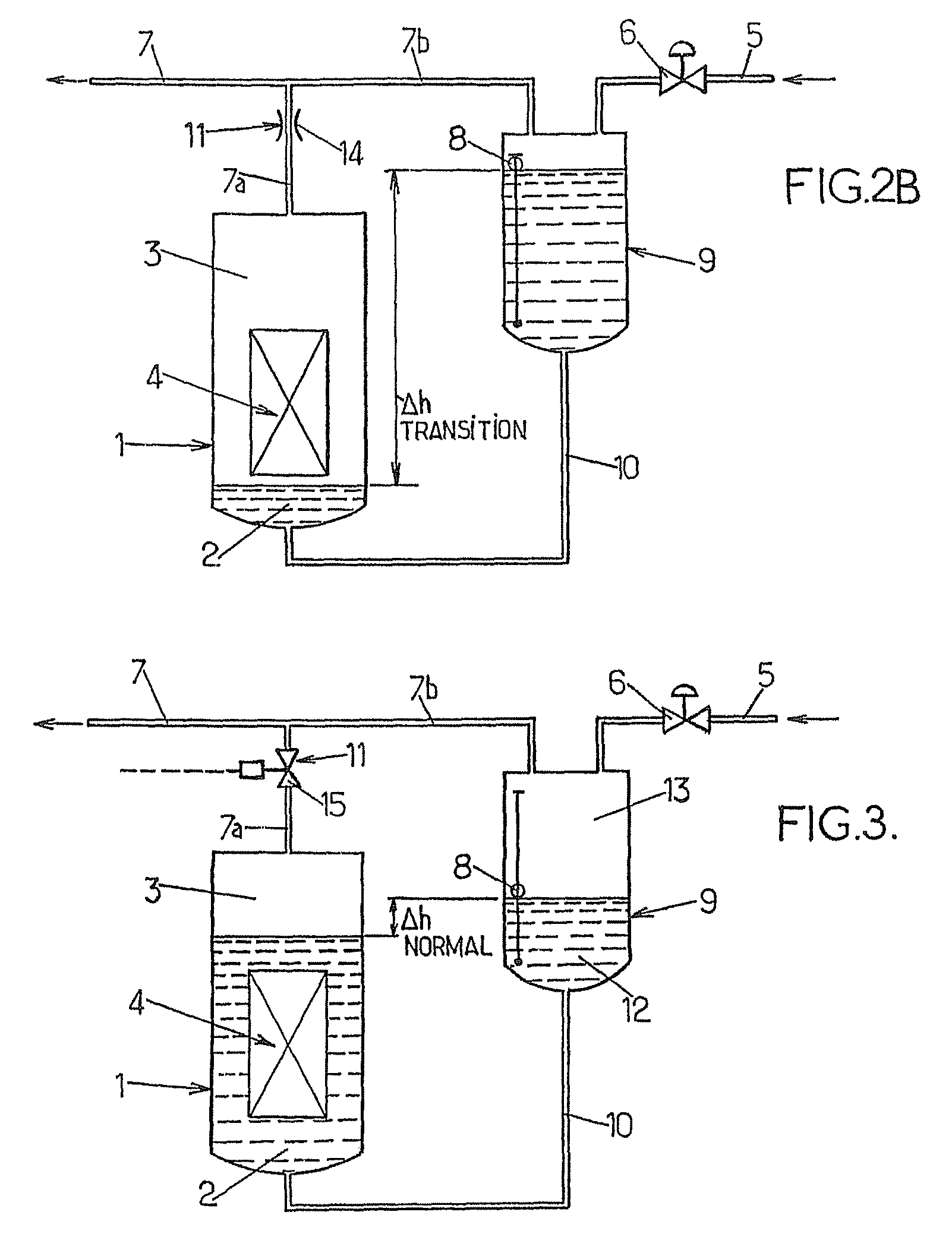
[0029]Referring now firstly to FIG. 2A, the installation arranged in accordance with the invention again comprises the elements shown in FIG. 1 but also with a second tank or auxiliary tank 9.

[0030]A hydrostatic connecting line 10 is interposed between the respective bottoms of the main 1 and auxiliary 9 tanks. The cryogenic fluid supply line 5, together with its control valve 6, is connected to the auxiliary tank 9 and the level gauge 8 is installed in the auxiliary tank 9.

[0031]The auxiliary tank 9 is also equipped with an outlet manifold 7b, while the outlet manifold 7a of the main tank 1 is provided with restricting means 11. As illustrated in FIG. 2A, the two manifolds 7a and 7b may be joined together, downstream of the restricting means 11, into a single manifold 7.

[0032]The auxiliary tank 9 is placed relative to the main tank 1 and is dimensioned so as to be able to accommodate at least a large part of the cryogenic fluid present in liquid form in the main tank 1. The auxilia...


PUM


Abstract

The invention concerns an installation for cryogenic cooling comprising: a main reservoir (1) for a two-phase cryogenic fluid wherein is immersed a superconductor device (4) to be cooled; an auxiliary reservoir (9); and a hydrostatic duct between the bases of the main and auxiliary reservoirs; the auxiliary reservoir being arranged relative to the main reservoir and being dimensioned so as to be able to receive at least a large part of the cryogenic fluid present in liquid form (2) in the main reservoir; restricting means (11) being incorporated in an output manifold (7a) connected to the main reservoir; thus, when the superconductor gets rapidly heated, cryogenic liquid from the main reservoir is delivered, by the vaporized cryogenic fluid pressure, into the auxiliary reservoir wherefrom it flows again by gravity towards the main reservoir when the pressure of the vaporized fluid decreases.

Description

BACKGROUND OF THE INVENTION[0001]1. Field of Invention[0002]The present invention relates in general to the field of installations for cryogenically cooling superconducting devices, and more particularly to improvements made to such installations comprising:[0003]a tank for a two-phase cryogenic fluid in which a superconducting device to be cooled is immersed;[0004]a cryogenic fluid supply line functionally associated with the tank in order to supply it with cryogenic fluid;[0005]a valve for controlling the supply of cryogenic fluid, which is placed in said supply line; and[0006]an outlet manifold connected to said tank.[0007]2. Description of Background Art[0008]A conventional arrangement of an installation according to the invention is illustrated in FIG. 1 of the appended drawing. A tank 1 contains a two-phase cryogenic fluid, the liquid phase 2 of which lies beneath a vapor phase 3. A superconducting device 4 is immersed in the liquid phase 2. A cryogenic fluid supply line 5 is ...

Claims


Application Information

Patent Timeline
Patent Type & Authority Patents(United States)
IPC IPC(8): F25B19/00
CPCF25B19/005F25D3/10F25B2500/01F25B2700/04H01F6/04
Inventor LEBRUN, PHILIPPEVULLIERME, BRUNO
Owner EUROPEAN ORGANIZATION FOR NUCLEAR RESEARCH
Why Eureka
Try Eureka