Adaptable tool hook

a tool hook and adaptable technology, applied in the field of tools and hangers, can solve the problems of scratching and injuring other people and objects, unable or convenient to put the tool down on the ground or the table, etc., and achieve the effect of convenient strapping to the tool, simple, inexpensive and effectiv

Active Publication Date: 2011-12-06
PIATT SR JOHN A +1
View PDF23 Cites 15 Cited by
  • Summary
  • Abstract
  • Description
  • Claims
  • Application Information

AI Technical Summary

Benefits of technology

[0008]An advantage of the present invention is a method and device are provided for hanging objects.
[0009]Another advantage of the present invention is that a method and device are provided that are simple, inexpensive, and effective.
[0010]A still further advantage of the present invention is that an adaptable hook is provided that can easily be strapped to a tool and then the tool can be hooked on a work-belt.

Problems solved by technology

But putting the tool down on the ground or table may not be possible or convenient.
The problem is the hook on the side of the worker can snag onto anything and can scratch and injure other people and objects.

Method used


Image

  • Adaptable tool hook
  • Adaptable tool hook
  • Adaptable tool hook

Examples


Embodiment Construction

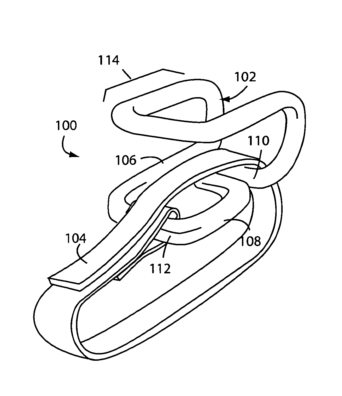
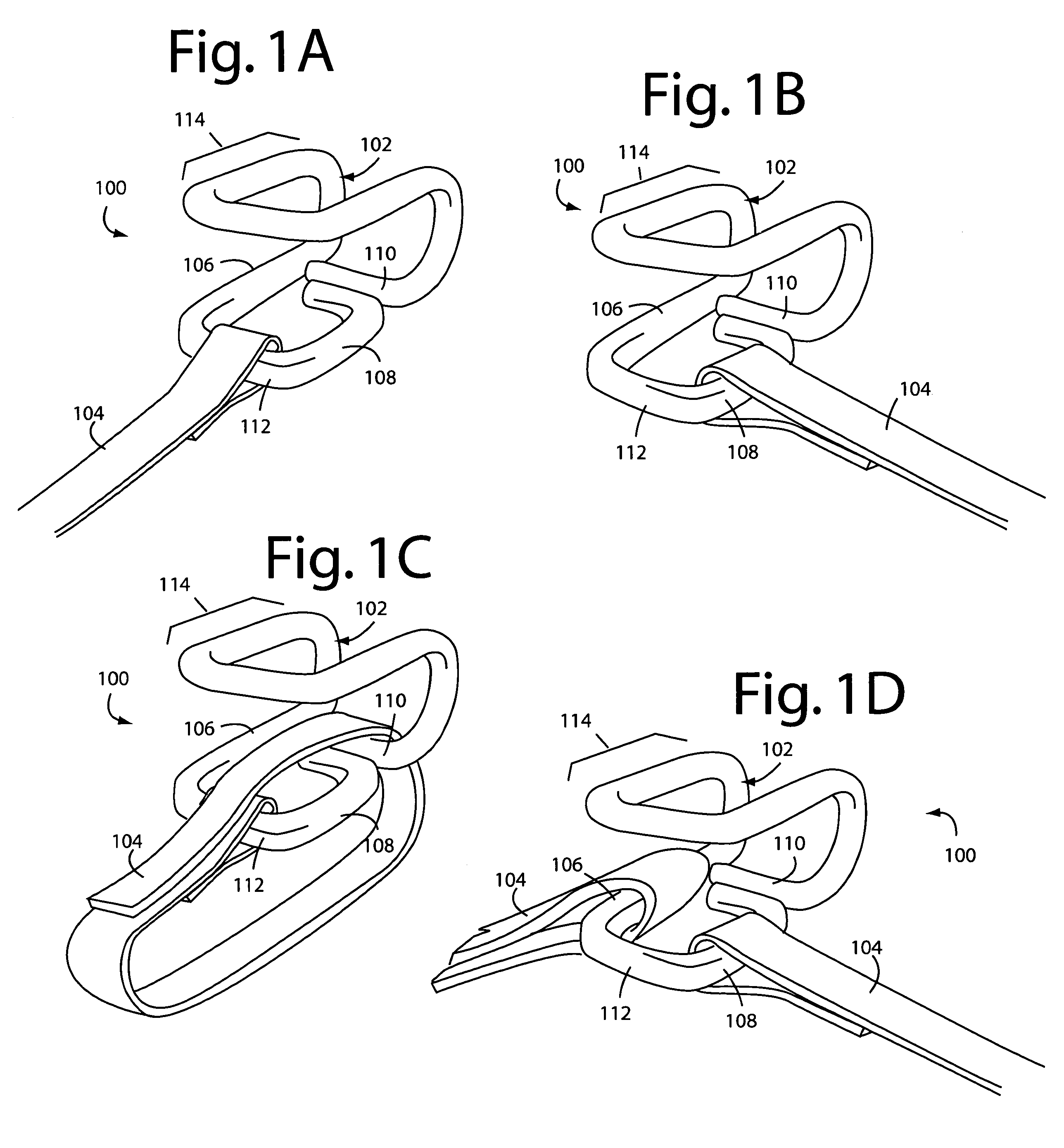
[0019]FIGS. 1A-1D illustrate an adaptable tool hook embodiment of the present invention, and is referred to herein by the general reference numeral 100. The adaptable tool hook 100 comprises a wire-frame buckle 102 and a strap 104. The buckle 102 has a left-lateral section 106, a right-lateral section 108, a top longitudinal section 110, and a bottom longitudinal section 112. These allow the strap 104 to be wrapped around an object with a hook section 114 being in-line or orthogonal.

[0020]FIGS. 1A and 1C illustrate strap 104 in its longitudinal starting position on section 112. FIGS. 1B and 1D illustrate strap 104 in its lateral starting position on section 108. The two positions are orthogonal to one another. The wire-frame construction is key to allowing strap 104 to be slipped between sections 106-108-110-112. In FIG. 1C, strap 104 can be doubled back around section 110, similar to the way shown in FIG. 1D.

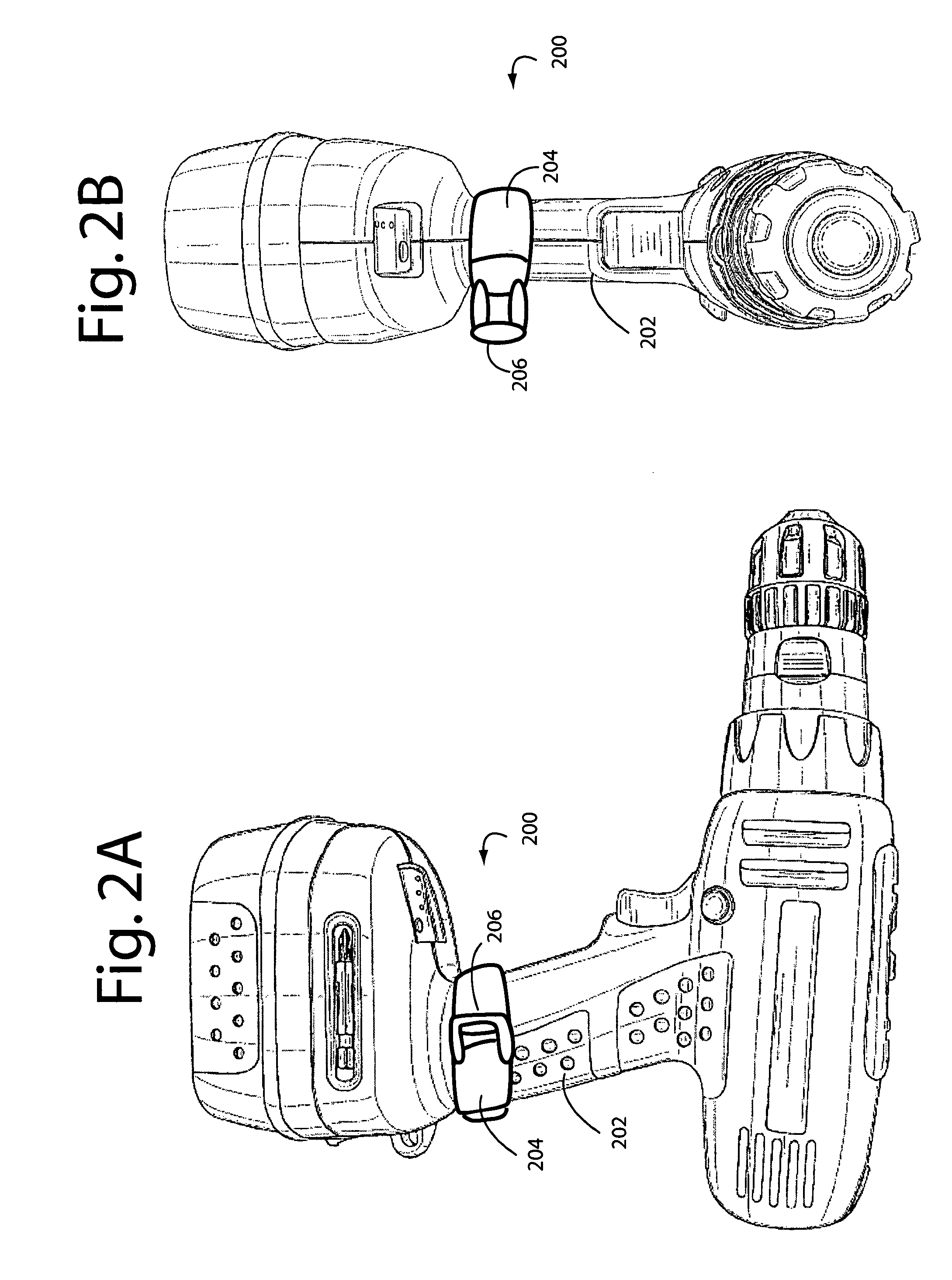
[0021]In use, the adaptable tool hook 100 can be strapped to any object th...


PUM


Abstract

An adaptable-tool hook comprises a wire-frame buckle and hook with a strap. The strap can be positioned on the buckle-hook in two different orthogonal positions to allow the strap to wrap an object or tool laterally or longitudinally. The hook stays with the tool and can be hooked on any available belt, pocket, rail, or wire.

Description

BACKGROUND OF THE INVENTION[0001]1. Field of the Invention[0002]The present invention relates to hooks and hangers, and more particularly to hooks that can be quickly strapped to a hand tool and thereafter easily be hung from a belt or pocket of a worker.[0003]2. Description of Related Art[0004]Only having “two hands” often requires that a worker put down a hand tool in order to complete some procedure or prepare it for using the tool. But putting the tool down on the ground or table may not be possible or convenient. So a variety of workers tool pouches, holsters and hooks have been devised and marketed.[0005]For example, a belt hook is shown by William Armstrong in U.S. Design Pat. No. D470,309 S, issued Feb. 18, 2003. Such appears to illustrate a saddle that can be threaded by a workers belt and worn on one side. A snap with a release lever allows a tool with a matching ring to be captured and held. Armstrong shows a variation of this idea in his U.S. Design Pat. No. D469,250 S, ...

Claims


Application Information

Patent Timeline
Patent Type & Authority Patents(United States)
IPC IPC(8): A45F5/00
CPCA45F5/02B25H3/00A45F5/021A45F2200/0575Y10S224/904
Inventor PIATT, SR., JOHN A.STAKEN, II, RICHARD S.
Owner PIATT SR JOHN A
Why Eureka
Try Eureka