Steer axle assembly

a technology of axle assembly and axle body, which is applied in the direction of resilient suspension, application, angiosperm/flowering plant, etc., can solve the problems of overloading and damage to any underlying pavement, requiring regular and frequent maintenance, and a relatively short li

Active Publication Date: 2011-12-06
2777216 ONTARIO
View PDF13 Cites 10 Cited by
  • Summary
  • Abstract
  • Description
  • Claims
  • Application Information

AI Technical Summary

Benefits of technology

[0009]Upper and lower kingpin seals are provided respectively adjacent the upper and lower yoke thrust faces and extending about to the kingpins to sealingly engage the kingpins for inhibiting the ingress of dirt and moisture into the yoke sleeves while allowing excess grease to escape.
[0010]The grease passage may extend along the kingpin into a cavity defined by a respective needle bearing sleeve surrounding each of the needle bearings. The grease passage may direct grease escaping from the lower yoke sleeve into the roller bearing to an interior of the roller thrust bearing from an inner diameter thereof. The roller thrust bearing is sealed about its outer periphery to inhibit ingress of dirt and moisture while allowing grease to be discharged therethrough.

Problems solved by technology

A challenge with adding an intermediate axle assembly is in steering the trailer when the wheels associated with the intermediate axle assembly are in contact with the underlying ground.
A problem with such an approach is that the weight carried by the intermediate axle assembly gets transferred to the remaining axles which may overload and damage any underlying pavement.
The thrust washer has facility for greasing but by its nature does not hold grease well as its faces press directly against the thrust faces of the components adjacent thereto.
Hence the thrust washer requires regular and frequent maintenance for any longevity and even with such treatment it tends to be relatively short lived.
The nature of bronze bushings is that they require frequent lubrication absent which their service life is very short and even with frequent lubrication the bushing life is relatively short.

Method used


Image

  • Steer axle assembly
  • Steer axle assembly
  • Steer axle assembly

Examples


Embodiment Construction

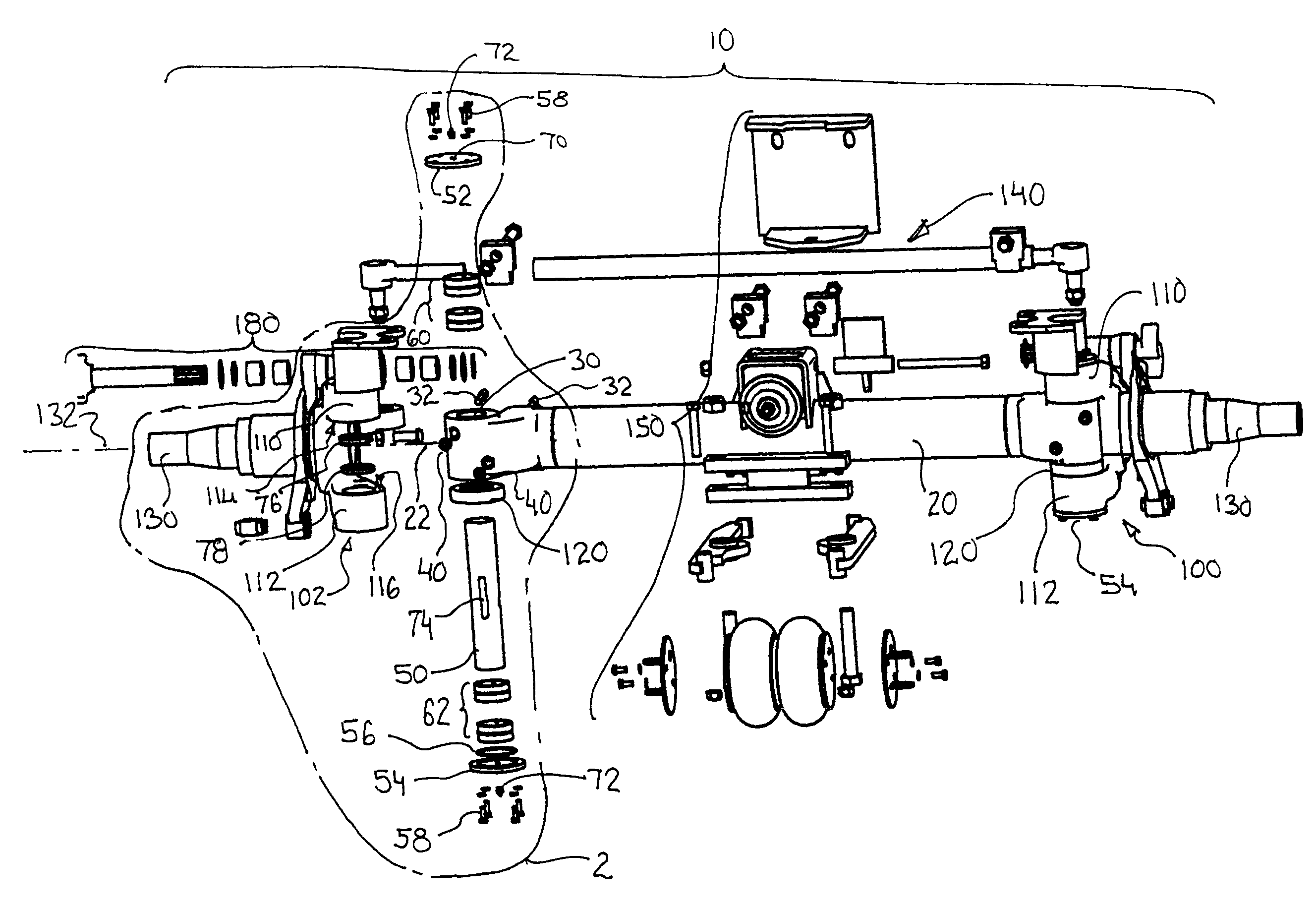
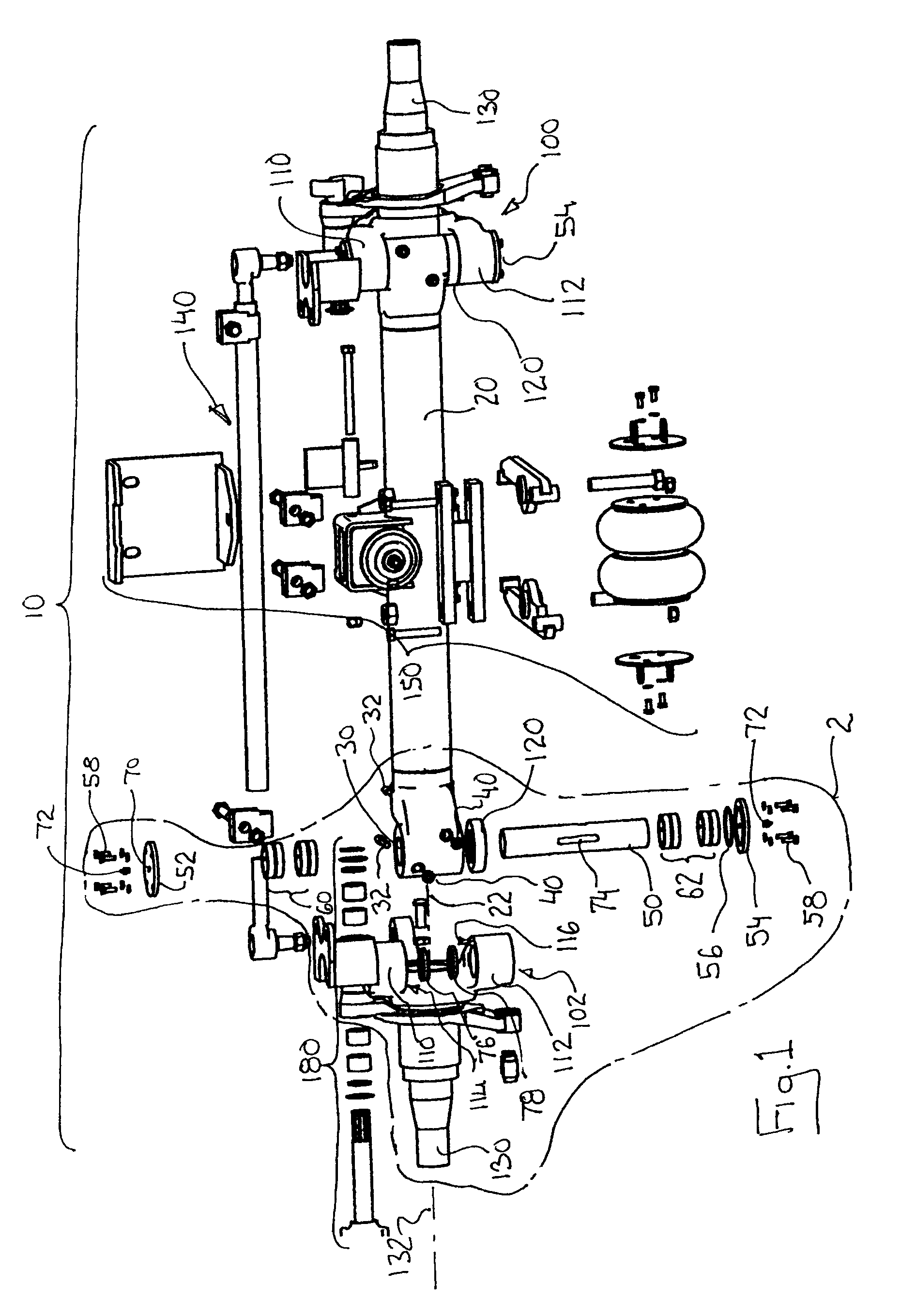
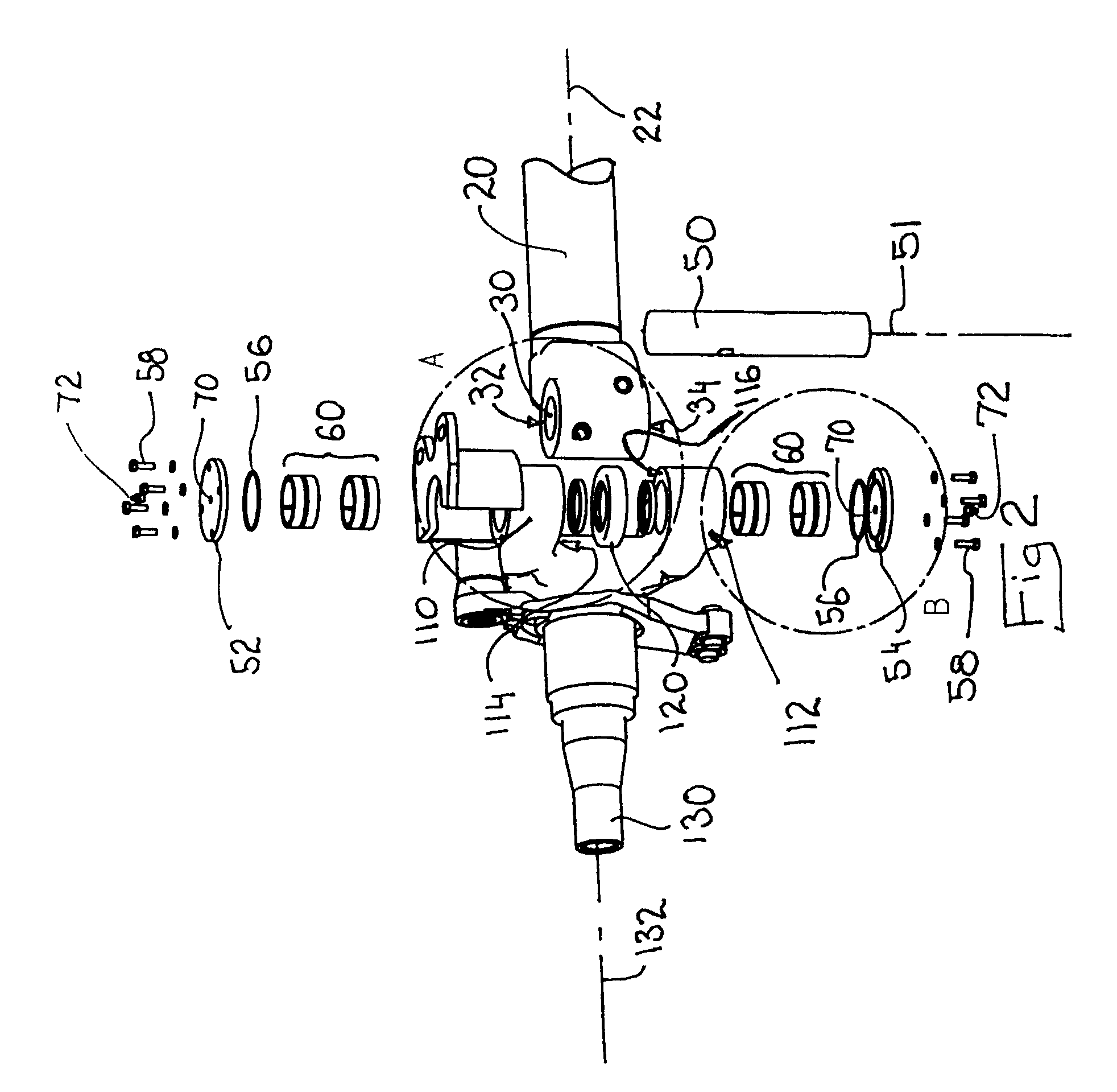
[0020]A steer axle assembly is generally indicated by reference 10 in the accompanying illustrations. The steer axle assembly 10 has a beam 20 which extends laterally between a left yoke 100 and a right yoke 102. The left yoke 100 and right yoke 102 are mirror images of each other and accordingly their components are indicated with common reference numerals as applicable and the description of one yoke applies equally to the other. The left and right yokes 100 and 102 respectively are swivelably mounted to opposite ends of the beam 10 by respective left and right kingpins 50 as described in more detail below.

[0021]The beam 20 has a beam axis 22. A respective kingpin sleeve 30 is rigidly secured to or integrate with opposite ends of the beam 10. Each kingpin sleeve 30 receives a kingpin 50 and supports the kingpin 50 to secure the kingpins 50 to the ends of the beam 10. Each kingpin 50 has a kingpin axis 51 which is generally orthogonal to the beam axis 22. The kingpin axes 51 are ge...


PUM


Abstract

An improved steer axle assembly for a trailer is provided in which a tapered roller thrust bearing extends between each lower kingpin yoke thrust face and each lower kingpin sleeve thrust face to transfer load between the lower yoke sleeve and the kingpin sleeve while allowing the yokes to swivel about the kingpins. Upper and lower needle bearing assemblies extend respectively between the upper and lower yoke sleeves and the kingpins to guide the swivelable movement of the yokes about the kingpins. Upper and lower kingpin caps are secured across the upper and lower yoke sleeves respectively above and below the kingpins to seal the opposite ends of the kingpins within the yoke sleeves. At least one of the upper and lower kingpin caps associated with each kingpin has a grease passage extending therethrough for admitting grease into an interior of the yoke sleeves and a grease fitting releaseably coupleable to a pressurized grease supply and sealingly engaging the grease passage to introduce grease into the grease passage.

Description

FIELD OF THE INVENTION[0001]The present invention relates to axle assemblies for trailers and more particularly to self-steering axle assemblies generally referred to as “steer axles”.BACKGROUND OF THE INVENTION[0002]The load carrying capacity of a truck trailer is determined by the number of axles it has, in other words on a “per axle” basis. In some instances carrying capacity of a trailer is enhanced by adding an intermediate axle assembly between the tractor wheelset and the rear wheelset of the trailer.[0003]A challenge with adding an intermediate axle assembly is in steering the trailer when the wheels associated with the intermediate axle assembly are in contact with the underlying ground. One solution to the problem is to raise the intermediate axle assembly to lift the associated wheels off of the ground in turns. A problem with such an approach is that the weight carried by the intermediate axle assembly gets transferred to the remaining axles which may overload and damage...

Claims


Application Information

Patent Timeline
Patent Type & Authority Patents(United States)
IPC IPC(8): B62D13/00
CPCB62D7/18
Inventor EVELEY, NICHOLAS
Owner 2777216 ONTARIO
Why Eureka
Try Eureka