Method and apparatus for automatically optimizing routing operations at the edge of a network

Active Publication Date: 2011-12-06
CISCO TECH INC
View PDF21 Cites 69 Cited by
  • Summary
  • Abstract
  • Description
  • Claims
  • Application Information

AI Technical Summary

Benefits of technology

[0022]The present invention overcomes the disadvantages of the prior art by providing an Optimized Edge Routing (OER) technique for efficiently routing data at the edge of a to network or subnetwork. The technique employs an OER Master node that manages a set of border nodes located at the edge of the network or subnetwork. Unlike prior implementations, the Master node instructs the border nodes to dynamically acquire (“learn”) prefixes and statistics of incoming and outgoing data flows matching a predetermined set of learn-filter criteria. The border nodes forward these learned prefixe

Problems solved by technology

Since management of a large number of subnetworks can prove burdensome, a network may contain smaller groups of one or more subnetworks which may be managed as separate routing domains or autonomous systems (AS).
Because BGP policies are applied to sequences of AS's, the policies are not able to optimize inter-AS routing in other respects, such as optimizing bandwidth utilization or minimizing cost or distance metrics.
Furthermore, interior gateway protocols cannot remedy these deficiencies in the BGP protocol because they do not scale well when applied to a large number of network nodes spanning multiple AS's.
For instance, the process of exchanging cost-based or distance-based routing metrics among a large number of network nodes would not only consume an unreasonable amount of network bandwidth, but

Method used


Image

  • Method and apparatus for automatically optimizing routing operations at the edge of a network
  • Method and apparatus for automatically optimizing routing operations at the edge of a network
  • Method and apparatus for automatically optimizing routing operations at the edge of a network

Examples


Embodiment Construction

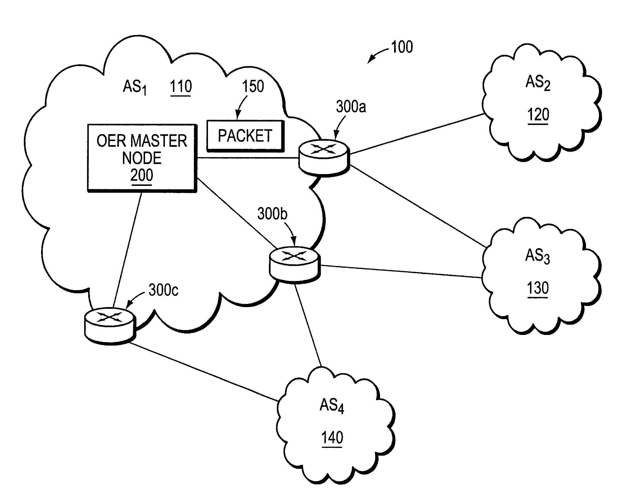
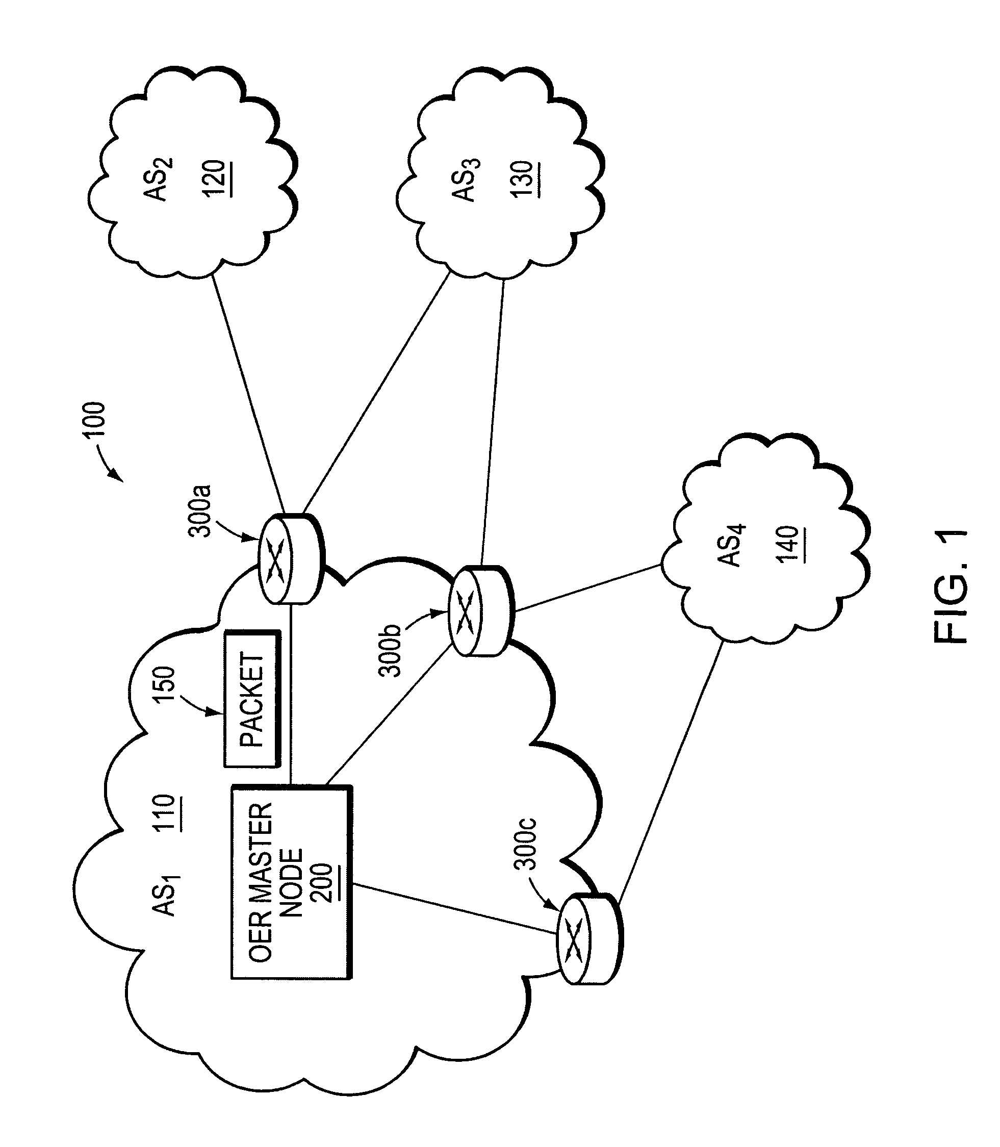
[0034]FIG. 1 is a schematic block diagram of an exemplary computer network 100 comprising a multi-homed autonomous system 110 (AS1) which is interconnected with a plurality of other autonomous systems 120, 130 and 140 (AS2-AS4). Illustratively, each AS1-AS4 is an autonomous system, although those skilled in the art will appreciate that the AS's 110-140 may be configured as routing domains or other networks or subnetworks. The autonomous system 110 includes one or more network nodes, including a set of border nodes 300a-c through which client communications, such as data flows, can pass into and out of the autonomous system. As shown, the border node 300a permits data packets 150 to be routed from AS1 to AS2 and AS3. The border node 300b enables nodes in AS1 to communicate with AS3 and AS4, and the node 300c is coupled to AS4. Routing operations at the border nodes 300a-c may be managed by an optimized edge routing (OER) “Master” node 200. The Master node may be connected to the bord...


PUM


Abstract

An Optimized Edge Routing (OER) technique provides efficiently data routing at the edge of a network or subnetwork. The technique employs a Master node that manages a set of border nodes located at the edge of the network or subnetwork. The Master node may be a stand-alone network management node or may be incorporated into a network node, such as a border node. Unlike prior implementations, the Master node instructs the border nodes to dynamically acquire (“learn”) prefixes of incoming and outgoing data flows and to selectively filter a set of learned address prefixes whose corresponding data flows match a predetermined set of criteria. The criteria may be based on routing metrics other than, or in addition to, conventional cost-based or distance-based metrics. Further, the criteria may include a set of filtering parameters that may be reconfigured, e.g., by the Master node, from time to time. Using the learned prefixes filtered by the border nodes, the Master node can distribute network traffic and utilize network bandwidth more efficiently than conventionally done.

Description

FIELD OF THE INVENTION[0001]This invention relates generally to routing data in a computer network, and, more specifically, to an Optimized Edge Routing (OER) technique that optimizes network traffic patterns at the edge of a network based on learned address prefixes.BACKGROUND OF THE INVENTION[0002]A computer network is a geographically distributed collection of interconnected subnetworks for transporting data between network nodes. A local area network (LAN) is an example of such a subnetwork. The network topology is defined by an arrangement of client nodes that communicate with one another, typically through one or more intermediate network nodes, such as a router or switch. As used herein, a client node is an endstation node that is configured to originate or terminate network communications. In contrast, an intermediate network node is a node that facilitates routing data and messages among the client nodes. Communications between network nodes are typically effected by exchan...

Claims


Application Information

Patent Timeline
IPC IPC(8): G06F15/173G06F15/16
CPCH04L45/00H04L45/04H04L43/0829H04L43/0852H04L43/0864H04L49/20
Inventor SHAH, PRITAMVALLURI, VAMSIDHARBLAIR, DANAJACOBS, PHILIP C.NGUYEN, KATHLEEN
Owner CISCO TECH INC
Why Eureka
Try Eureka