Pipe protector

a technology of pipe support and protector, which is applied in the direction of machine supports, domestic objects, applications, etc., can solve the problems of rupturing of pipes and relatively labor-intensive installation process, and achieve the effects of preventing compression of insulation materials, facilitating linear movement of pipes, and reducing potential damage to insulation materials

Active Publication Date: 2011-12-13
ARMACELL ENTERPRISE GMBH & CO KG
View PDF11 Cites 21 Cited by
  • Summary
  • Abstract
  • Description
  • Claims
  • Application Information

AI Technical Summary

Benefits of technology

[0012]The pipe support member of the instant invention is designed to support insulated pipes—i.e. the pipe has a layer of insulation wrapped thereabout. Thus, it is important to minimize potential damage to the insulation when it sits within the pipe support member.
[0013]To this end, at both ends of the pipe support member, there is preferably provided an arrangement wherein the inner surface of the tongues slope downwardly and are terminated by rounded lips. The extended tongues and lips are shaped to allow linear movement of the pipe during expansion and contraction such that the insulated material thereabout is not subject to tearing and breakage.
[0014]In a further preferred aspect, the interior wall of the pipe support member preferably has a textured finish which creates a film of air between the pipe support holder and pipe insulation material to facilitate linear movement of the pipe with its insulation material within the member. The length of the pipe support member may be designed to prevent compression of the insulation material.

Problems solved by technology

Initially, each pipe must be installed individually and as such, the installation process is relatively labour intensive.
Secondly, the hangers can cause the rupturing of the pipes after a period of time.
This would occur due to movement of the pipe within the pipe hanger and subsequent surface damage.

Method used


Image

  • Pipe protector
  • Pipe protector
  • Pipe protector

Examples


Embodiment Construction

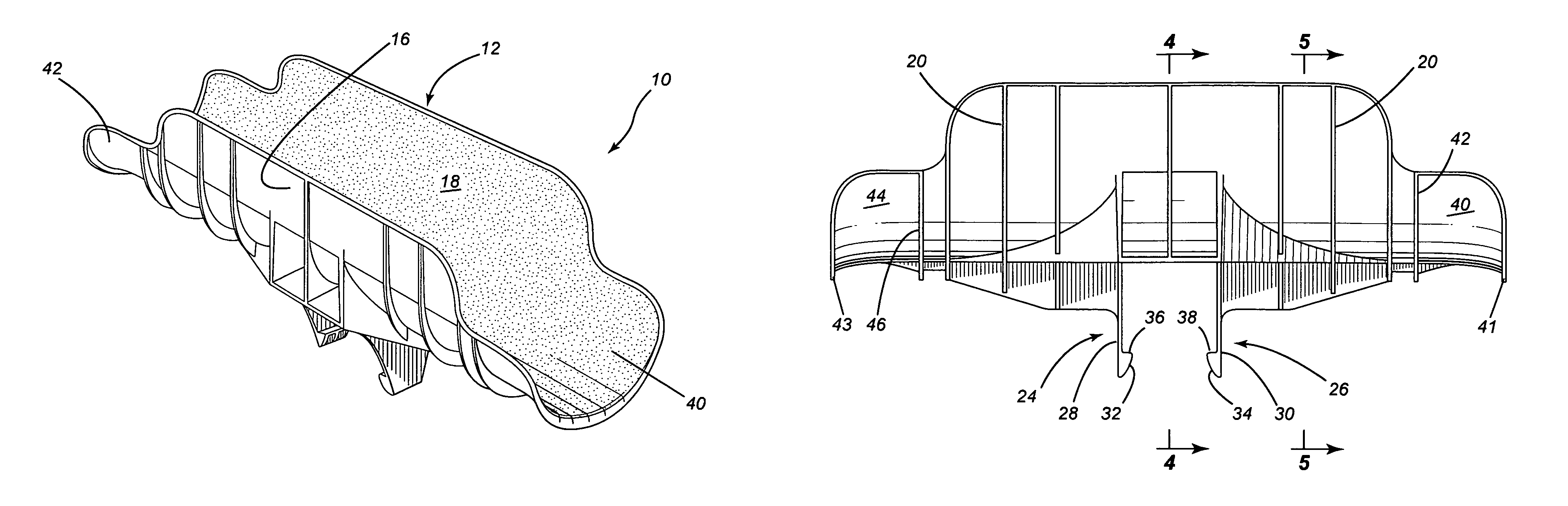
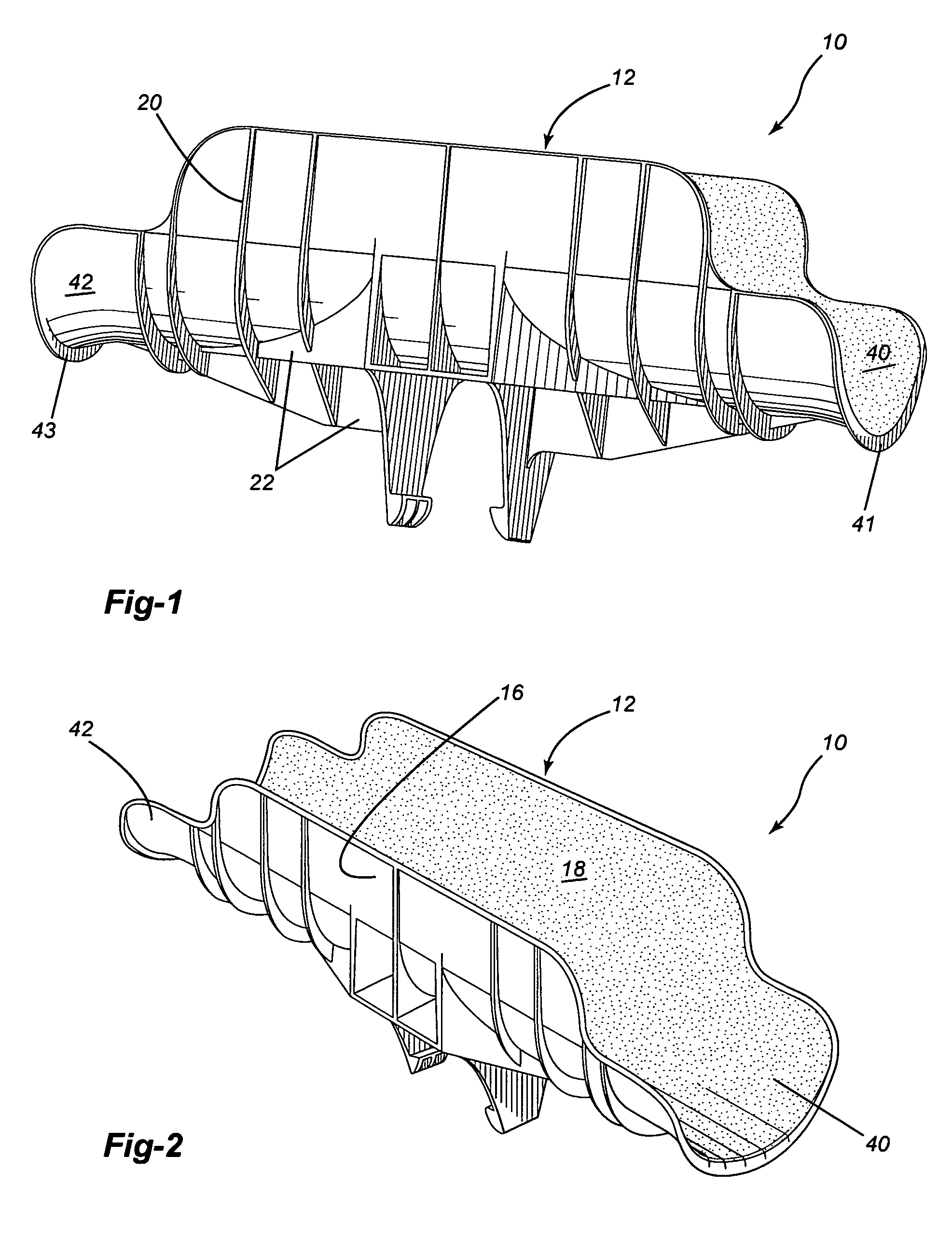
[0025]Referring to the drawings in greater detail and by reference characters thereto, there is illustrated a pipe support member which is generally designated by reference numeral 10.

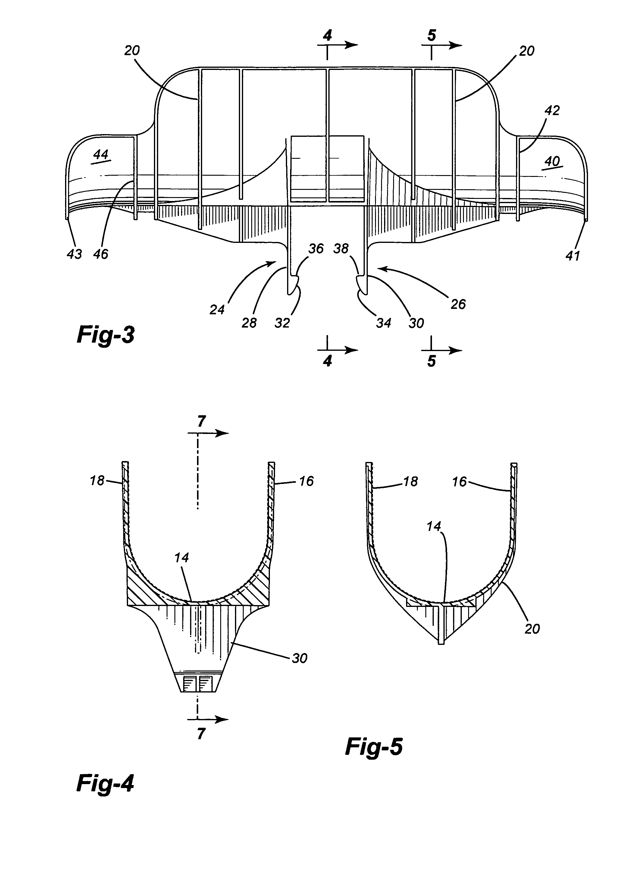
[0026]Pipe support member 10 includes a central body portion generally designated by reference numeral 12 and which comprises a bottom wall 14 which is of an arcuate configuration and upwardly extending sidewalls 16 and 18.

[0027]On the exterior facing surface of bottom wall 14 and sidewalls 16, 18, there are spaced transverse flanges 20. Flanges are also provided along the longitudinal extending flanges 22, three such flanges being illustrated.

[0028]The pipe support member 10 is designed to be attached to a truss type support and to this end, there are provided a pair of fastening or clamping members generally designated by reference numerals 24 and 26. Fastening members 24, 26 each have a respective sidewall 28, 30 which extends outwardly from the bottom wall 14. Each sidewall 28, 30 in turn has respe...


PUM


Abstract

A pipe support which comprises a body having a recess of a generally U-shaped configuration formed therein, the recess being opened at a top end, the body having a clamping portion extending downwardly and which clamping portion includes first and second resilient members which each comprise a vertical sidewall and an inwardly extending end segment. The pipe support is particularly suitable for use on various structural members.

Description

[0001]The present application is a continuation in part of application Ser. No. 10 / 966,568 filed Oct. 15, 2004 now abandoned.FIELD OF THE INVENTION[0002]The present invention relates to a pipe support system.BACKGROUND OF THE INVENTION[0003]In the installation of pipes and the like in various types of buildings and in particular pipes associated with air conditioning, refrigeration and heating, such as may be employed in commercial and industrial establishments, conventional practice is that the pipes are hung from the ceiling by strap hangers.[0004]The most common type of strap hanger employed in the industry comprises a metal strap having apertures for fastening purposes. The strap is looped about the pipe to be secured and then a fastening member such as a screw or the like is secured to a substrate such as a beam or rafter through the apertures.[0005]This conventional means of fastening pipes suffers from several disadvantages. Initially, each pipe must be installed individually...

Claims


Application Information

Patent Timeline
Patent Type & Authority Patents(United States)
IPC IPC(8): E21F17/02
CPCF16L3/221F16L3/24
Inventor BOUDREAU, MARTINTHIBAULT, JEAN-PIERRE
Owner ARMACELL ENTERPRISE GMBH & CO KG
Why Eureka
Try Eureka