
Mechanical stop for axle/suspension systems

a technology of suspension system and mechanical stop, which is applied in the direction of resilient suspension, spring/damper, vehicle components, etc., can solve the problems of reducing the amount of cargo that can be carried by the heavy-duty vehicle, adding varying degrees of complexity and prior art shock absorbers adding complexity and weight to the axle/suspension system

Active Publication Date: 2014-07-17
HENDRICKSON USA L L C
View PDF2 Cites 2 Cited by
  • Summary
  • Abstract
  • Description
  • Claims
  • Application Information

AI Technical Summary

Benefits of technology

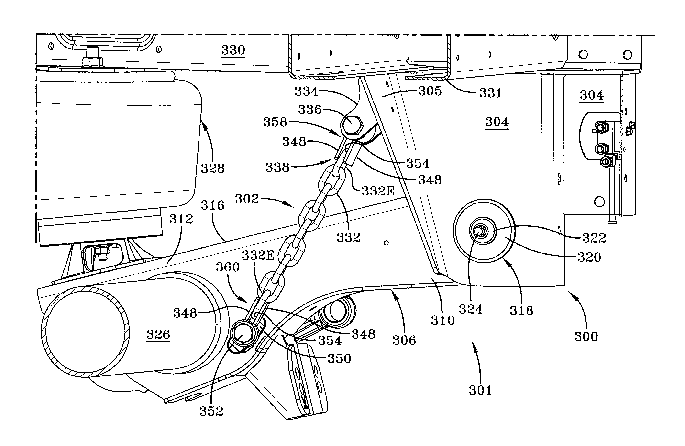
The present invention aims to provide a mechanical stop for axle / suspension systems that can prevent the axle / suspension system from moving too far downward. This may be important in situations where there is no need for a shock absorber. Additionally, the invention seeks to minimize potential damage to the air spring and other components of the axle / suspension system.

Problems solved by technology

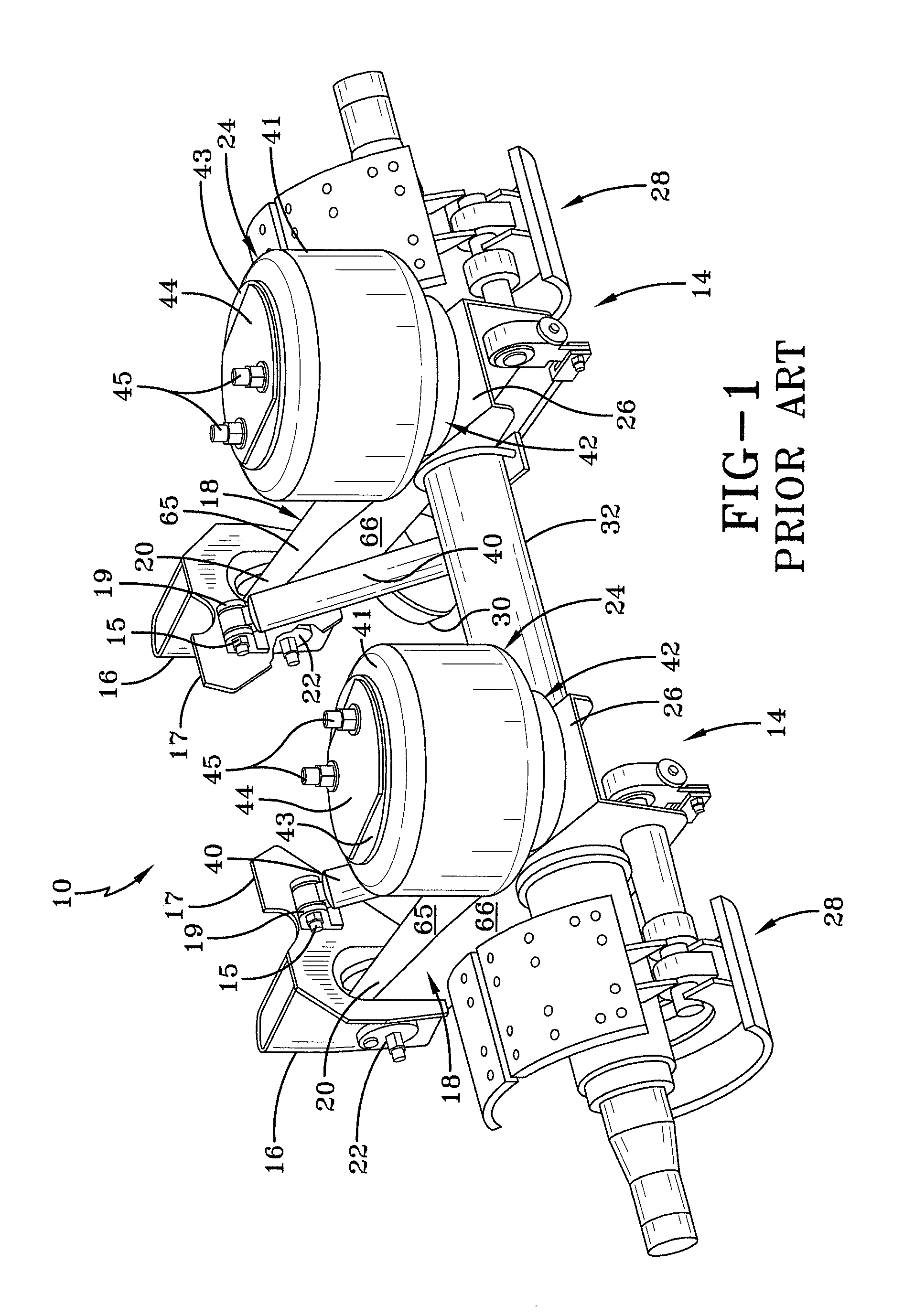
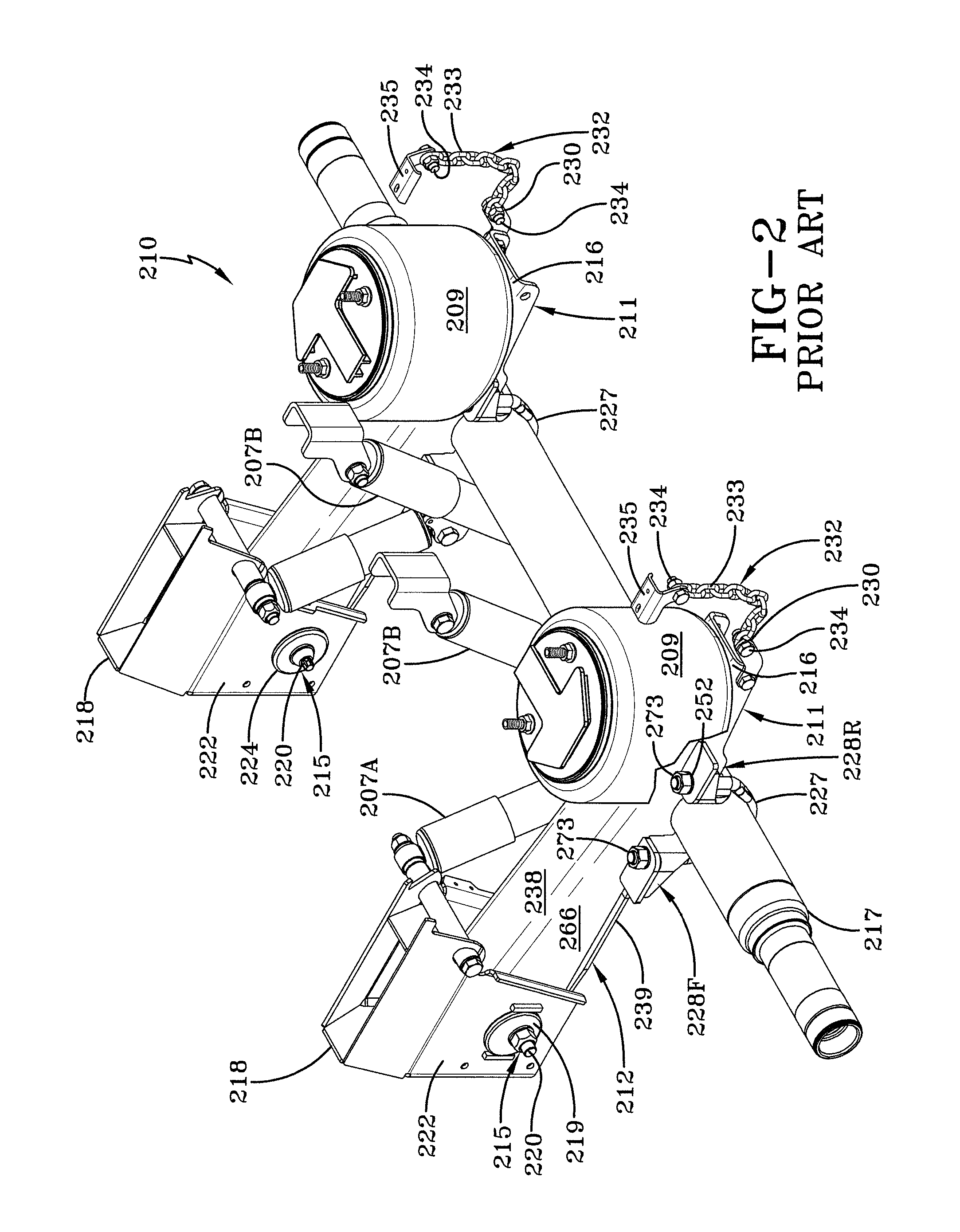
Because shock absorbers are relatively heavy, these components add undesirable weight to the axle / suspension system and therefore reduce the amount of cargo that can be carried by the heavy-duty vehicle.
Depending on the shock absorbers employed, they also add varying degrees of complexity to the axle / suspension system which is also undesirable.
Prior art shock absorbers add complexity and weight to the axle / suspension system.
Moreover, because prior art shock absorbers are a service item of the axle / suspension system that require maintenance and / or replacement from time to time, they also add additional maintenance and / or replacement costs to the axle / suspension system.
Prior art shock absorbers, while providing damping characteristics, also limit the downward movement of the beam of the axle / suspension system minimizing the possibility of damage to the air spring and to the axle / suspension system.
For example, when a trailer is lifted onto a railroad car, the prior art shock absorber limits downward movement of the beam of the axle / suspension system, which if not limited could potentially result in damage to the air spring and axle / suspension system.
The elimination of the prior art shock absorber may potentially lead to issues with downward movement of the axle / suspension system, as described previously.
More specifically, the air spring and / or the axle / suspension system may be potentially damaged if the beam of the axle / suspension system overextends downwardly as a result of the trailer being lifted onto a railroad car, “reverse braking”, and / or if the trailer encounters a pot hole or other obstacle.

Method used


Image

  • Mechanical stop for axle/suspension systems
  • Mechanical stop for axle/suspension systems
  • Mechanical stop for axle/suspension systems

Examples


first embodiment

[0059]Semi-circular portion 446 of generally U-shaped connector 438 generally encircles elastomeric bushing 440. Elastomeric bushing 440 is preferably composed of rubber, but may include other elastomeric compositions or may include some other member of compliance, such as a spring, and is generally cylindrical in shape. Elastomeric bushing 440 includes a continuous centrally-formed opening 456. A cylindrical inner sleeve 444 is disposed in opening 456 by press fit or other connection type, such as adhesive, and inner sleeve includes an opening 442. Elastomeric bushing 440 is in turn generally press-fit into semi-circular portion 446 of connector 438. Inner sleeve 444 facilitates connection of stop 402 to suspension assembly of axle / suspension system as described in first embodiment mechanical stop 302.

second embodiment

[0060]An important aspect of second preferred embodiment mechanical stop 402 is flexible sleeve 403. Sleeve 403 may be composed of a durable material, such as a composite, form-fitting rubberized coating, or other flexible covering. Sleeve 403 is formed with an opening 407 through which links 432 are disposed to enclose or encase and minimize the movement of the links. Further, sleeve 403, which may be in a single piece or with a seam, is generally cylindrical in shape and generally extends the length of links 432 to limit the movement of the links. More specifically, sleeve 404 limits lateral movement, vertical movement, and crimping movement as well as other potentially detrimental movements of links 432. The limited movement of links 432 in turn minimizes the impact of the links upon the beam 406 of the axle / suspension system 401 and prolongs the product life of second embodiment mechanical stop 402 (FIG. 11). Optionally, a pin assembly 409 (FIG. 8) may be included in second pref...


PUM


Abstract

An axle / suspension system for heavy-duty vehicles having a frame and at least one suspension assembly operatively connected to the frame, the axle / suspension system including a mechanical stop having a plurality of links and a first end and a second end, the second end rigidly attached to the suspension assembly and the first end rigidly attached to the vehicle frame, wherein the first end and the second end control a distance between the first end and the second end, and control the plurality of links to attain a movement tolerance range of said mechanical stop from about 0.0 inches to about 2.0 inches.

Description

CROSS-REFERENCE TO RELATED APPLICATIONS[0001]This application claims the benefit of U.S. Provisional Patent Application Ser. No. 61 / 753,689, filed Jan. 17, 2013, and U.S. Provisional Patent Application Serial No. 61 / 805,364, filed on Mar. 26, 2013.BACKGROUND OF THE INVENTION[0002]1. Field of the Invention[0003]The invention relates generally to the art of axle / suspension systems for heavy-duty vehicles. More particularly, the invention relates to air-ride axle / suspension systems for heavy-duty vehicles which utilize an air spring to cushion the ride of the vehicle. More specifically, the invention relates to a mechanical stop for use with an axle / suspension system that utilizes an air spring with damping characteristics that is lightweight and limits the downward movement of the beam of the axle / suspension system to minimize potential damage to the air spring and the axle / suspension system during operation of the vehicle.[0004]2. Background Art[0005]The use of air-ride trailing and ...

Claims


Application Information

Patent Timeline
Patent Type & Authority Applications(United States)
IPC IPC(8): B60G99/00
CPCB60G99/002B60G9/003B60G11/27B60G13/10B60G2204/4504B60G2300/026F16F1/3849F16F2230/007
Inventor ANDREASEN, JACOBFULTON, R. SCOTTRAMSEY, JOHN E.LIPPINCOTT, RYAN J.
Owner HENDRICKSON USA L L C
Learn More