Electrical fluid activated switch

a technology of electric fluid and switch, which is applied in the direction of liquid/fluent solid measurement, instruments, machines/engines, etc., to achieve the effects of low manufacturing cost, convenient and efficient manufacturing and marketing, and durable and reliable construction

Inactive Publication Date: 2008-01-01
HERNANDEZ ZELAYA RODOLFO
View PDF8 Cites 6 Cited by
  • Summary
  • Abstract
  • Description
  • Claims
  • Application Information

AI Technical Summary

Benefits of technology

[0021]It is therefore an object of the present invention to provide a new and improved electrical field activated switch which has all of the advantages of the prior art switches of known designs and configurations and none of the disadvantages.
[0022]It is another object of the present invention to provide a new and improved electrical field activated switch which may be easily and efficiently manufactured and marketed.
[0023]It is further an object of the present invention to provide a new and improved electrical field activated switch which is of durable and reliable constructions.
[0024]An even further object of the present invention is to provide a new and improved electrical field activated switch which is susceptible of a low cost of manufacture with regard to both materials and labor, and which accordingly is then susceptible of low prices of sale to the consuming public, thereby making such electrical field activated switch economically available to the buying public.
[0025]Even still another object of the present invention is to provide an electrical field activated switch for allowing a user to safely and conveniently control the fluid level of a container by having a switch control the fluid flow level of a container by having a switch control the fluid flow from the container.

Problems solved by technology

While these devices fulfill their respective, particular objectives and requirements, the aforementioned patents do not describe an electrical field activated switch that allows allowing a user to safely and conveniently control the fluid level of a container by having a switch control the fluid flow level of the container.

Method used


Image

  • Electrical fluid activated switch
  • Electrical fluid activated switch
  • Electrical fluid activated switch

Examples


Embodiment Construction

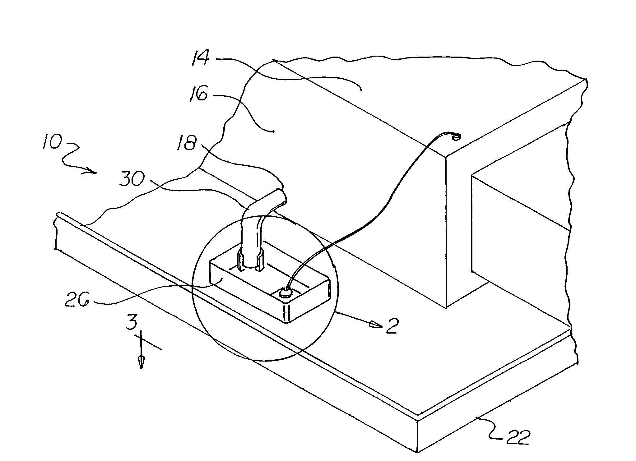
[0035]With reference now to the drawings, and in particular to FIG. 1 thereof, the preferred embodiment of the new and improved electrical field activated switch embodying the principles and concepts of the present invention and generally designated by the reference numeral 10 will be described.

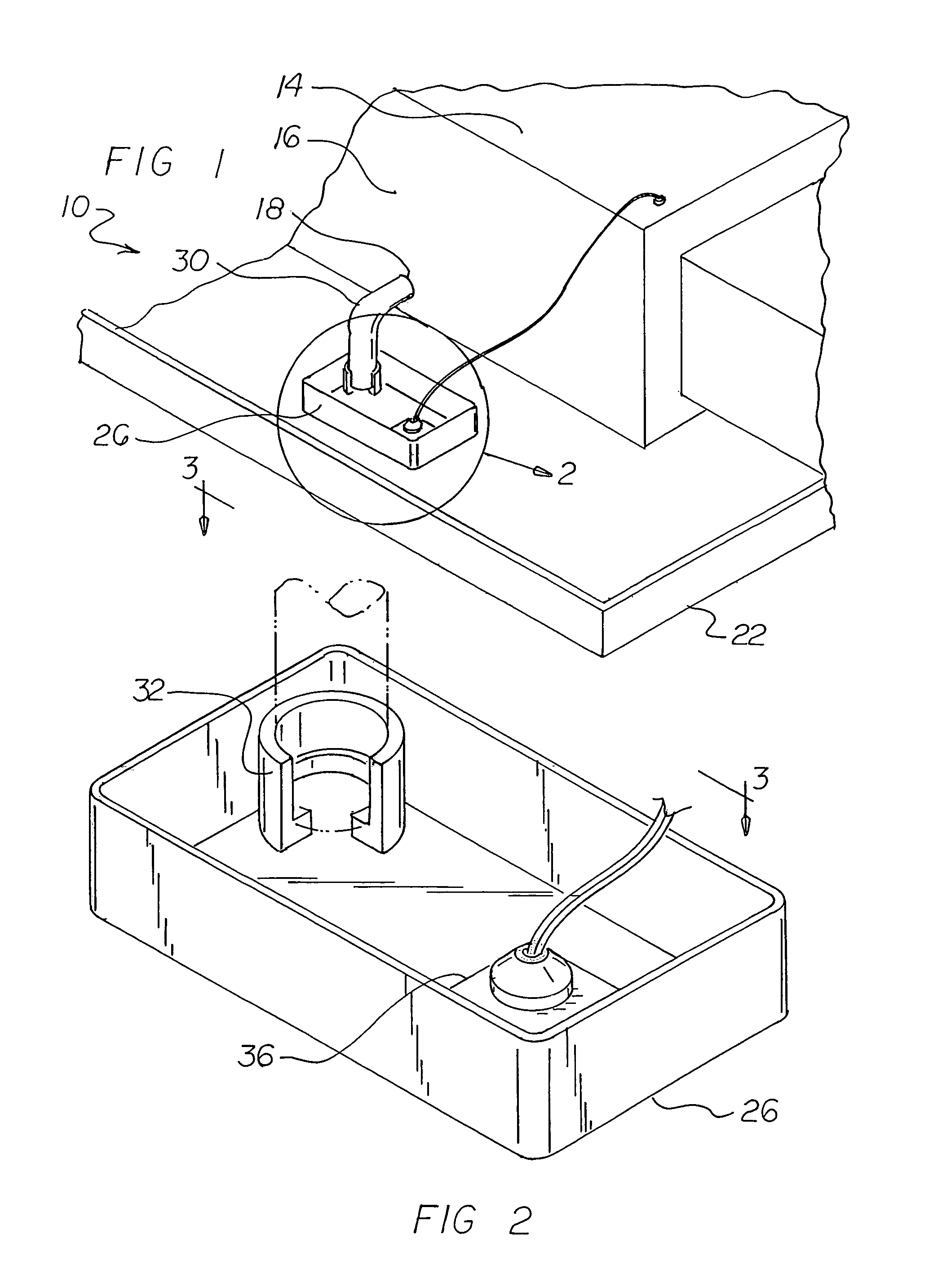
[0036]The present invention, the electrical field activated switch system 10 is comprised of a plurality of components. Such components in their broadest context include a container, a primary tray, a secondary tray, a tube, a housing and an electrical induction switch. The system functions for allowing a user to reliably and conveniently control the fluid level of a container by having a switch control a fluid flow device. The system comprises, in combination, a fluid container 14 with a side wall 16 and an aperture 18 formed in the side wall. The container is adapted to accumulate fluid during operation and use and to cause the flow of accumulated fluid, when above a predetermined level, fr...


PUM


Abstract

An electrical field activated switch system includes a fluid container 14 having an aperture formed in a sidewall thereof. The floor of the primary tray 22 is positioned entirely beneath the fluid container and a secondary tray is positioned entirely within the primary tray and in proximity to and at an elevation beneath the aperture. A tube 30 is coupled between the aperture and the secondary tray. A housing 36 has an open bottom secured to the secondary tray with a cylinder 38 vertically oriented therein. A base 40 is supported upon the secondary tray floor. An electrical induction switch assembly includes two wires with stripped lower ends positioned within the cylinder with their lower ends being separated and in proximity to the base. A float is slidably received upon the cylinder with a magnetic plate secured to the float.

Description

RELATED APPLICATION[0001]The present application is a continuation-in-part of pending U.S. patent application Ser. No. 10 / 961,492 filed Oct. 8, 2004 which is a continuation-in-part of U.S. patent application Ser. No. 10 / 447,054 filed May 28, 2003, now U.S. Pat. No. 7,009,125, which, in turn, is a continuation-in-part of U.S. patent application Ser. No. 10 / 224,811 filed Aug. 21, 2002, now abandoned.BACKGROUND OF THE INVENTION[0002]1. Field of the Invention[0003]The present invention relates to an electrical field activated switch and more particularly pertains to allowing a user to safely and conveniently control the fluid level of a container by having a switch control the fluid flow level of the container.[0004]2. Description of the Prior Art[0005]The use of switches of known designs and configurations is known in the prior art. More specifically, switches of known designs and configurations previously devised and utilized for the purpose of controlling the fluid level of a contain...

Claims


Application Information

Patent Timeline
Patent Type & Authority Patents(United States)
IPC IPC(8): G01F23/30
CPCG01F19/00
Inventor HERNANDEZ-ZELAYA, RODOLFO
Owner HERNANDEZ ZELAYA RODOLFO
Why Eureka
Try Eureka