Trolley attachment

a technology of trolleys and studs, which is applied in the field of trolleys, can solve the problems of rusting of threaded studs, nuts may eventually slide off or detach from studs, and labor intensive, and achieve the effect of easy assembly and quick attachmen

Inactive Publication Date: 2005-10-06
FROST TECH
View PDF7 Cites 5 Cited by
  • Summary
  • Abstract
  • Description
  • Claims
  • Application Information

AI Technical Summary

Benefits of technology

[0011] The attachment element of the load bar to the trolley thus does not require any threaded fasteners and, thus, substantially obviates the corrosion concerns of the prior art. Also, the attaching member may be readily attached to the load bar without having to tighten any threaded fasteners to a desired torque to retain the load bar thereon. The shaft portion of the attaching member may limit longitudinal and lateral movement of the load bar relative to the attaching portion, while the end or head portion limits downward movement of the load bar relative to the attaching member. The attachment or spacer element comprises a unitarily or integrally formed element, with the end portion, the shaft portion and the base portion being unitarily formed. The present invention thus provides a robust attachment assembly or system that also may be readily assembled by an operator at the conveying system.

Problems solved by technology

In order to attach the load bar to the trolley or trolleys, an operator must thread and tighten the nut onto the stud, which may be labor intensive.
Also, when the material handling system and trolleys are implemented in caustic environments, concerns exist with the durability of the threaded stud and nut.
For example, chemicals and / or the like that may be encountered in such caustic environments may lead to corrosion of the threaded stud, whereby the nut may eventually slide off or detach from the stud.
This may cause the load bar to detach from the trolley and fall to the ground, which is a safety concern and may also be damaging to the trolley and the material conveyed by the trolley and to the facility.
Although some applications may include a cotter pin or the like through the nut to retain the nut to the stud, the cotter pins are often not robust enough and may shear under the loads applied by the load bar.

Method used


Image

  • Trolley attachment
  • Trolley attachment
  • Trolley attachment

Examples


Embodiment Construction

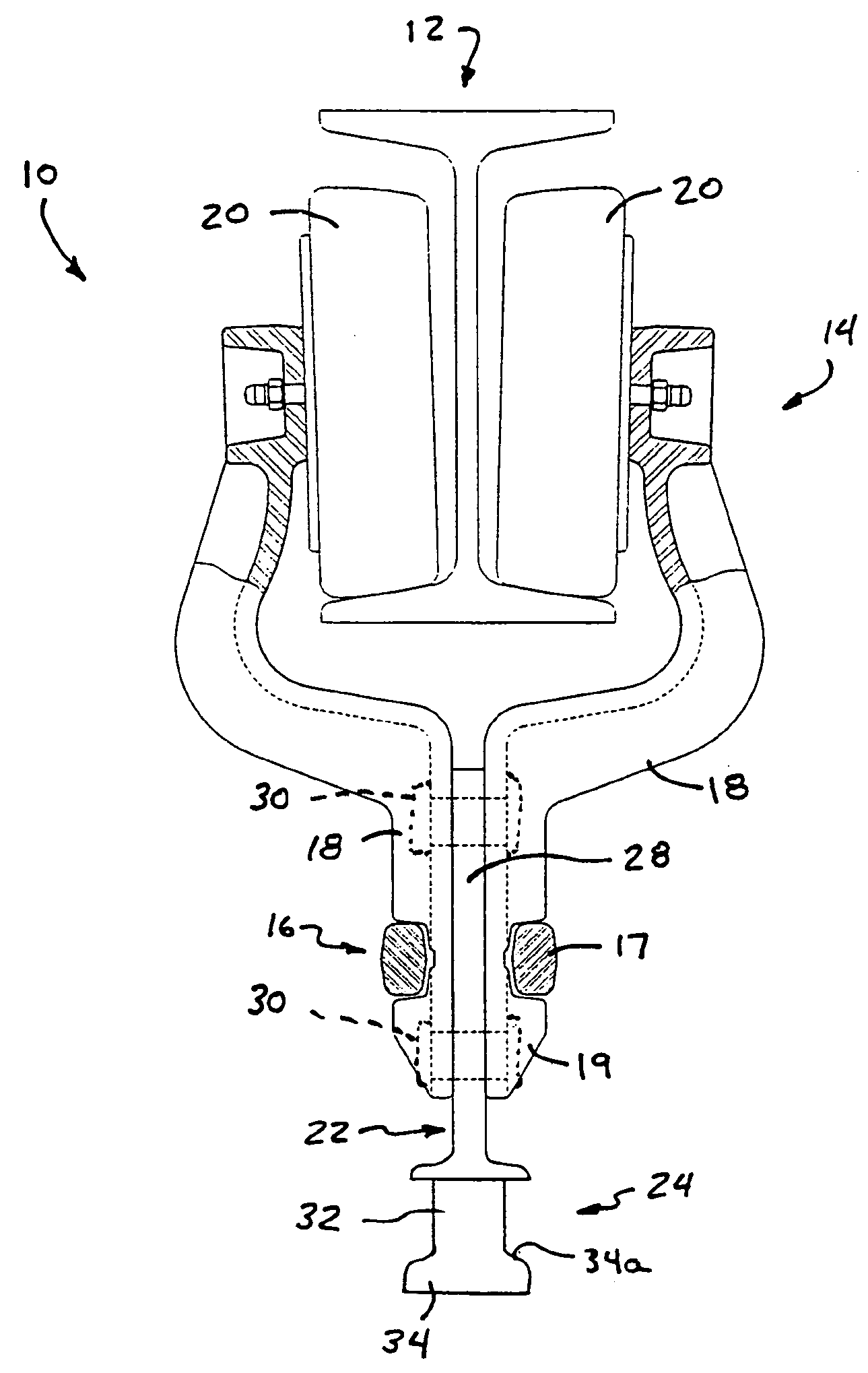
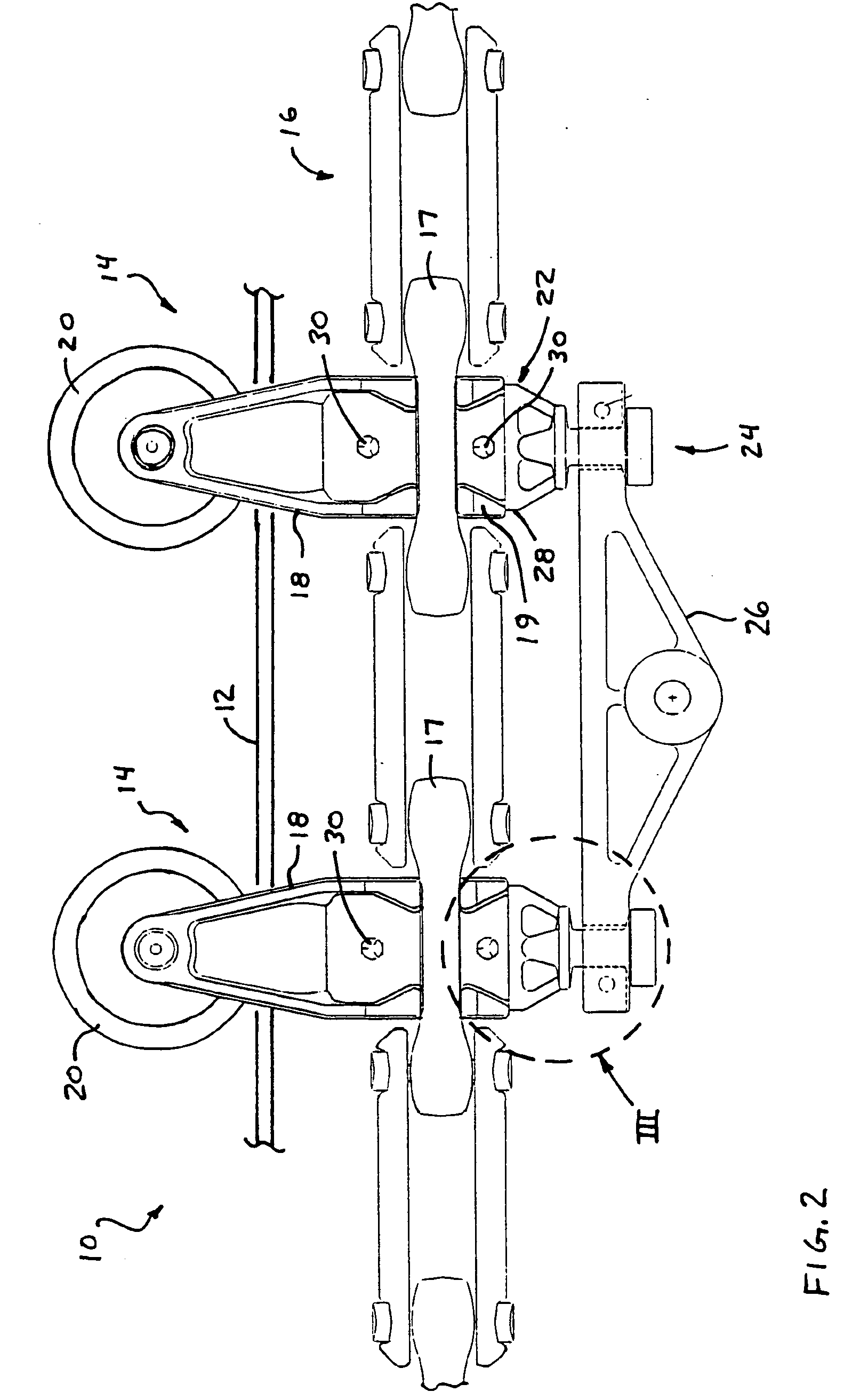
[0019] Referring now to the drawings and the illustrative embodiments depicted therein, a conveying system or trolley system 10 includes a conveying track 12 and a plurality of trolleys 14 which are movable along conveying track 12 via a chain 16 (FIG. 2). Each trolley 14 includes at least one trolley arm 18 (and may include a pair of trolley arms as shown in FIG. 4), each of which includes a trolley wheel 20 at an upper end thereof for rolling along conveying track 12, as discussed below. Trolley arms 18 extend downward from wheels 20 and are secured together at a lower portion thereof about a spacer or attachment element 22. Spacer or attachment element 22 includes a load bar attaching member 24 extending downwardly therefrom for attaching the trolley to a load bar 26, as discussed below. Trolley arms 18 may connect to one or more chain links 17 of chain 16, such that movement of chain 16 drives or moves trolley 14 along the conveying track 12. Conveying track 12 may include oppos...


PUM


Abstract

A trolley for a conveying system includes a first trolley arm with a trolley wheel rotatably mounted thereon, a second trolley arm with a trolley wheel rotatably mounted thereon, and a load bar. The trolley wheels roll along a track of the conveying system to move the trolleys along the conveyor track. The first trolley arm connects to a first attachment element, which includes a base portion and an attaching member that are integrally formed together. The load bar connects to the second trolley arm and to the attaching member of the first attachment element. The load bar has a slot proximate to one or both ends for receiving the attaching member. The attaching member is retainable in the slot, such as via a retaining pin. The first and second trolley arms are connected together via the load bar.

Description

CROSS REFERENCE TO RELATED APPLICATION [0001] The present application claims benefit of U.S. provisional application Ser. No. 60 / 521,345, filed Apr. 6, 2004, which is hereby incorporated herein by reference in its entirety.FIELD OF THE INVENTION [0002] The present invention relates generally to trolleys and, more particularly, to trolleys for material handling and conveying systems. BACKGROUND OF THE INVENTION [0003] It is known to provide a trolley which is movable along a conveyor track, such as an I-beam track or a pair of oppositely facing C-channel tracks. The trolley typically includes a pair of opposite arm portions which include a corresponding trolley wheel for engaging a respective one of the channels or tracks. The trolley arms are secured together about a spacer or attachment, which fits between the lower portions of the trolley arms to facilitate attachment of the trolley arms to the chain which drives the trolley along the track. As shown in FIG. 1, a typical spacer 2 ...

Claims


Application Information

Patent Timeline
Patent Type & Authority Applications(United States)
IPC IPC(8): B61B3/00B61B10/02B65G17/20B65G35/06
CPCB65G17/20B61B10/022
Inventor WALDMILLER, LEE R.
Owner FROST TECH
Why Eureka
Try Eureka