Flexible down tube and methods of use thereof

a flexible down tube and dispenser technology, applied in the direction of liquid handling, single-unit apparatus, instruments, etc., can solve the problems of wasting money, reducing the efficiency of bottle use, and reducing the use of bottle assembling, so as to achieve the effect of reliably using and inexpensive production

Active Publication Date: 2009-12-29
SC JOHNSON & SON INC
View PDF18 Cites 5 Cited by
  • Summary
  • Abstract
  • Description
  • Claims
  • Application Information

AI Technical Summary

Benefits of technology

[0017]In another form the invention provides methods of assembling such a liquid dispensing device with a container having a bottom wall, side wall structure, an internal reservoir cavity, liquid in the cavity and an upper opening. One obtains such a container and also a liquid dispensing device. One then inserts the down tube of such a device into the internal reservoir cavity of the container. This moves the essentially rigid member / sleeve from a first position in which it restricted pivoting of the lower section relative to the upper section during the inserting step, to a second position where it permits the lower section to pivot relative to the upper section in the internal cavity. Most preferably during this moving step a flange of the rigid member contacts the container, to thereby restrict downward movement of the flange while driving the rigid member up along the down tube as the down tube is inserted in the internal cavity.
[0018]When the down tube of the present invention is fully assembled with the container the lower end of the down tube will be free to sway / pivot / flex as the container is tipped, even though the lower end of the dip tube is rigid. However, importantly, the overall down tube structure can be essentially rigid during the assembly of the sprayer / down tube subassembly with the bottle. This permits conventional equipment to be used to assemble the sprayer to the bottle, and further permits higher line speeds to be consistently used.
[0021]The sleeve / flange member can be inexpensively produced and reliably used. For example, it can be formed of a plastic such as high density polyethylene, polypropylene, nylon, etc. As will be discussed below, there are sealing advantages to selecting a material for the flange member which is softer than the material against which it will abut.
[0023]These assemblies are constructed so that the sprayer can be removably attached (preferably threaded) to the container. This permits the container to be refilled when empty, or alternatively replaced by another filled container, without the need to dispose of the sprayer unit (which can have a much longer useful life).

Problems solved by technology

This can lead to air being sucked into the down tube (resulting in an undesired air / liquid foaming mix), or can result in the consumer throwing away the bottle prematurely, or can restrict how a consumer can effectively use the bottle.
While flexible pick-up tubes of this type are quite advantageous, there is some difficulty in assembling them with the bottles when using high speed, automated equipment.
This can slow line speed, require specialized equipment, and / or create occasional breakage during the assembly process.

Method used


Image

  • Flexible down tube and methods of use thereof
  • Flexible down tube and methods of use thereof
  • Flexible down tube and methods of use thereof

Examples


Embodiment Construction

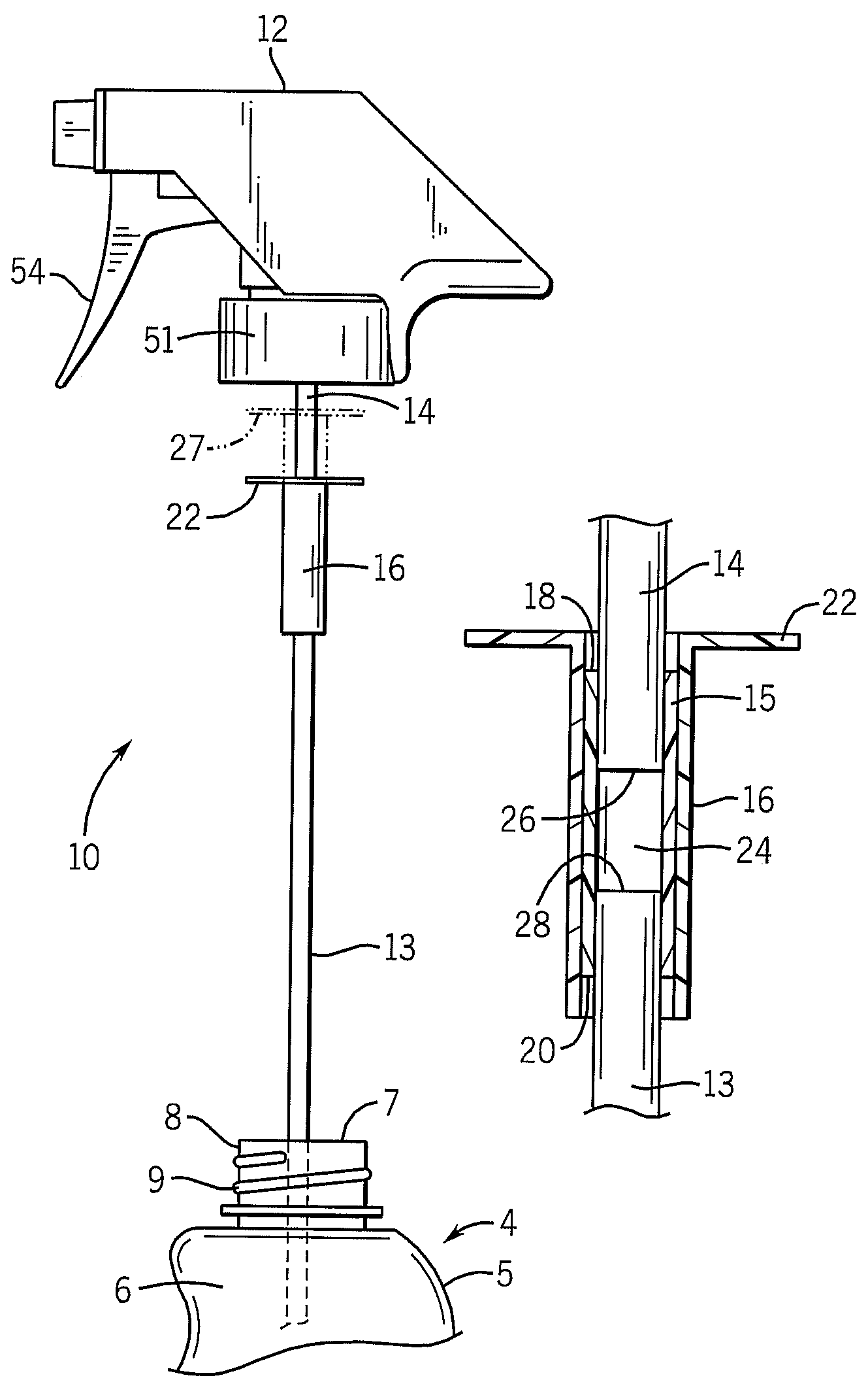
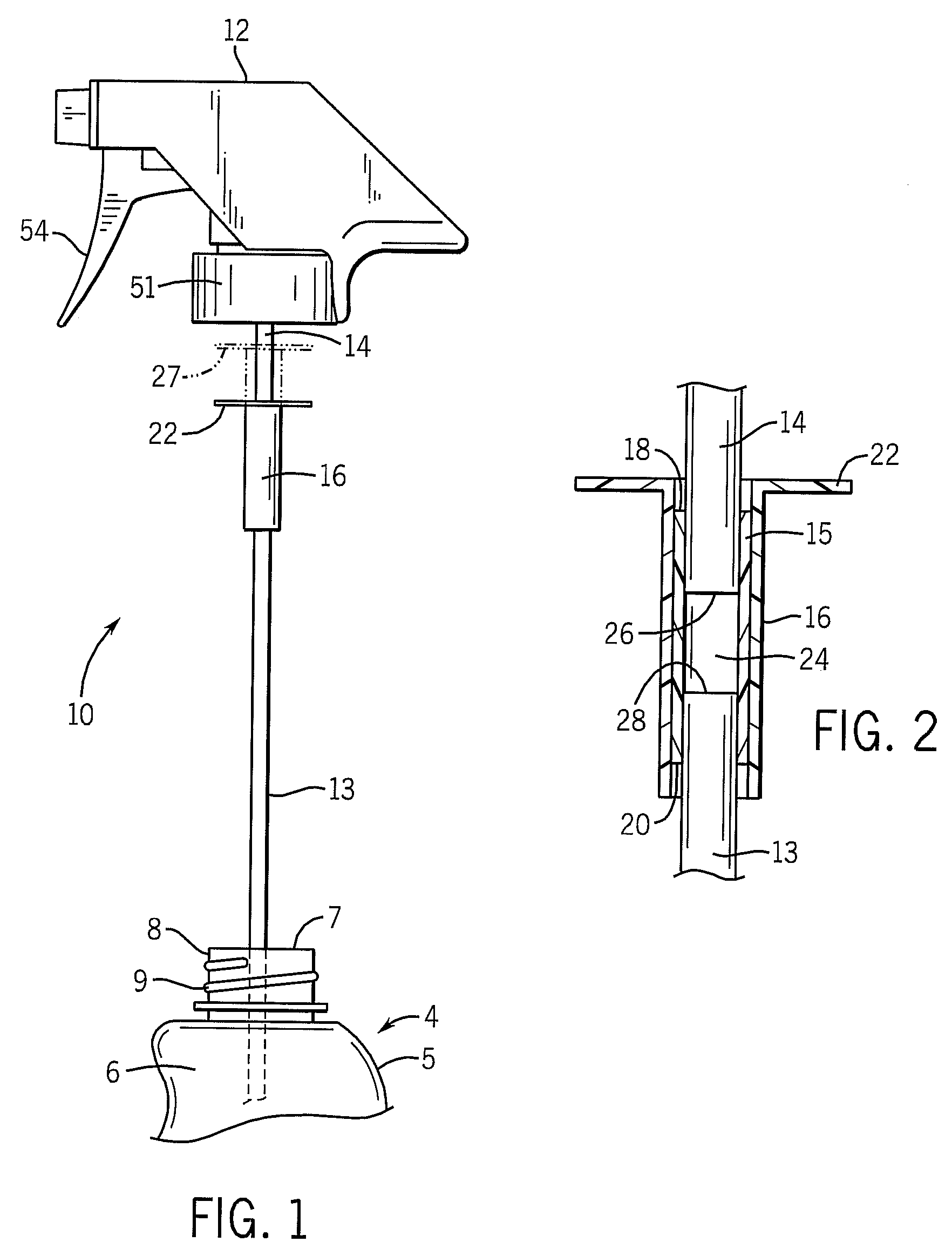
[0031]The dispenser of the present invention is suitable for use with a conventional container 4 having a conventional bottom wall (not shown), side wall structure 5, internal cavity 6, upper opening 7 and associated lip 8. See also U.S. Pat. No. 5,518,150 for the example of other containers.

[0032]As can be seen from FIG. 1, a down tube assembly 10 of the present invention is designed to be linked to sprayer / liquid dispenser 12. The down tube assembly 10 of this embodiment comprises an essentially rigid lower section 13, an essentially rigid upper section 14, and (as can be seen for example from FIG. 2) an intermediate flexible section 15 in the form of a flexible tubular sleeve. The lower end 26 of upper section 14, the upper end 28 of lower section 13, and the intermediate flexible section 15, are surrounded by a rigid sleeve 16 when the dispensing device is ready for assembly to the container.

[0033]The upper end 18 of the intermediate flexible section 15 and the lower end 20 of t...


PUM


Abstract

Disclosed are liquid dispensing devices suitable for use to dispense liquid from a container. They have a conventional sprayer associated with a flexible down tube. The down tube has an essentially rigid upper section linked to the sprayer, an essentially rigid lower section suitable to extend into the container, and an intermediate flexible section. An essentially rigid member (e.g. a sleeve) is mounted on / to the down tube so as to move between a first position in which it covers the flexible section so as to restrict pivoting of the lower section relative to the upper section, to a second position in which it permits the lower section to pivot relative to the upper section. As the down tube is being inserted in the container a flange on the sleeve is held by the container lip so that the sleeve is caused to move between the two positions. The down tube structure is thus rigid during assembly of the tube with the container, but automatically becomes flexible thereafter. Methods of assembly are also disclosed using these structures.

Description

CROSS-REFERENCE TO RELATED APPLICATIONS[0001]Not applicable.STATEMENT REGARDING FEDERALLY SPONSORED RESEARCH / DEVELOPMENT[0002]Not applicable.BACKGROUND OF THE INVENTION[0003]The present invention relates to spray dispensers having a flexible down tube to facilitate spraying when a bottle or other container associated with the dispenser is not completely vertical. More particularly it relates to such devices that are configured to facilitate automated, high speed assembly of such dispensers with containers holding the liquids to be dispensed.[0004]A variety of devices are known for delivering liquid from a container. Some rely on aerosol valves to deliver the spray. See e.g. U.S. Pat. No. 5,797,522. Others rely on trigger pump sprayers. See e.g. U.S. Pat. No. 6,789,303. Still others use motorized pumping systems.[0005]Some use a down (a / k / a “pick-up”; a / k / a “dip”) tube that extends from the sprayer unit down into the container holding the liquid to be dispensed. The upper end of the ...

Claims


Application Information

Patent Timeline
Patent Type & Authority Patents(United States)
IPC IPC(8): B05B11/00B05B15/00B65D3/14B67D7/58B67D7/78
CPCB05B11/0059B65D83/32B05B15/005B05B15/30
Inventor CONWAY, SIMON M.HARRITY, KEVIN
Owner SC JOHNSON & SON INC
Why Eureka
Try Eureka