Connecting element for electric conductors with a printed circuit board

a technology of connecting elements and printed circuit boards, which is applied in the manufacture of contact parts, coupling device connections, fixed connections, etc., can solve the problems of frequent reuse of dismounted connecting elements, and achieve the effects of reliable contact, easy and fast disassembly, exchange and reus

Active Publication Date: 2011-12-13
HARTING ELECTRIC GMBH & CO KG
View PDF10 Cites 17 Cited by
  • Summary
  • Abstract
  • Description
  • Claims
  • Application Information

AI Technical Summary

Benefits of technology

In the contact region, the electric contact of the connecting element is realized in the form of a sleeve-like part with a bulgy distention and features at least one axial slot. The diameter of this sleeve-like contact region is elastically reduced in the axial direction during the insertion into an opening, wherein said contact region approximately reassumes its original shape once it is correctly seated. The clamping pin is inserted into the contact region in this state such that the contact region is clamped against the inner surface of the opening. A control of the electric contacting is not necessary because the clamping pin can only be inserted into the contact if the contact is correctly seated in the opening. Consequently, optimal seating and reliable contacting of the connecting element on the printed circuit board can be ensured.
The purely elastic deformations of the contact region during the mounting and dismounting on / from the printed circuit board make it possible to exchange the connecting element and / or to reuse the connecting element in another opening.
A termination that is situated in the terminal region of the electric contact and serves for connecting an electric conductor may be realized in different ways. Aside from a simple surface or eye for soldering on the electric conductor, it is advantageous to realize the termination in the terminal region such that it is suitable for crimping. An electric conductor can be solidly connected to the is electric contact on this termination with a normal crimping tool.
In another preferred embodiment, the terminal region of the electric contact is also realized in a sleeve-like fashion, however, with a larger diameter than that of the contact region being inserted into the opening in the printed circuit board. The inner side of the terminal region features a constriction and a disk-shaped section formed on the clamping pin engages behind said constriction. A second disk-shaped section formed on the head of the clamping pin is provided for allowing a simple removal of the clamping pin.
It is furthermore proposed to mount connecting elements on a printed circuit board in a positioning frame. This positioning frame may be realized in such a way that several connecting elements can be simultaneously accommodated. Encoding pins provided on the positioning frame prevent mismating of the mounting direction.
The advantages attained with the invention can be seen, in particular, in that reliable contacting is ensured with the connecting element, and in that the mounting can be realized without the utilization of tools and, if so required, even with one hand only. In addition, the connecting element and all components used can be easily and quickly dismounted, exchanged and reused.

Problems solved by technology

The dismounted connecting element frequently cannot be reused due to a destructive dismounting.

Method used


Image

  • Connecting element for electric conductors with a printed circuit board
  • Connecting element for electric conductors with a printed circuit board
  • Connecting element for electric conductors with a printed circuit board

Examples


Embodiment Construction

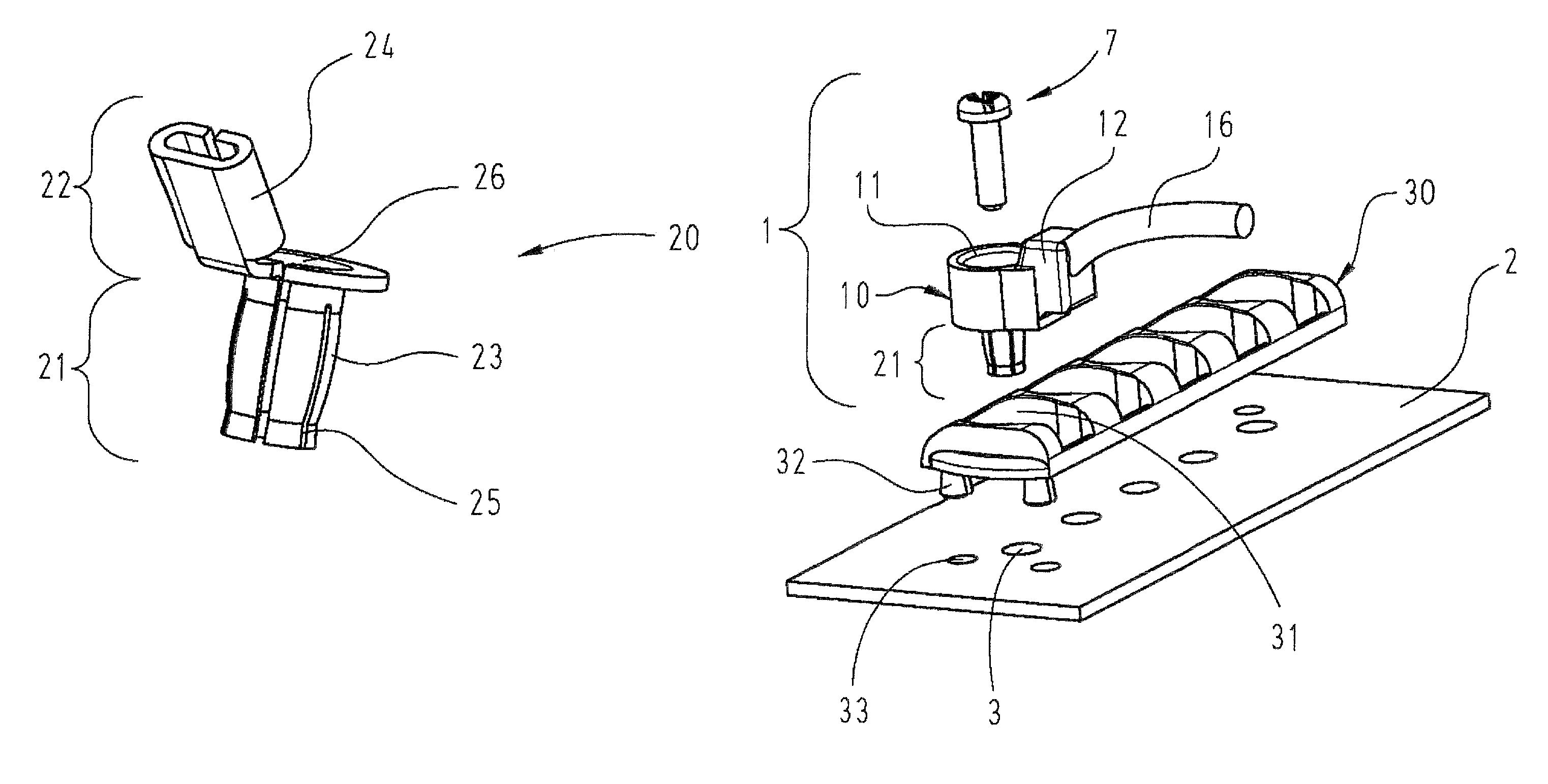
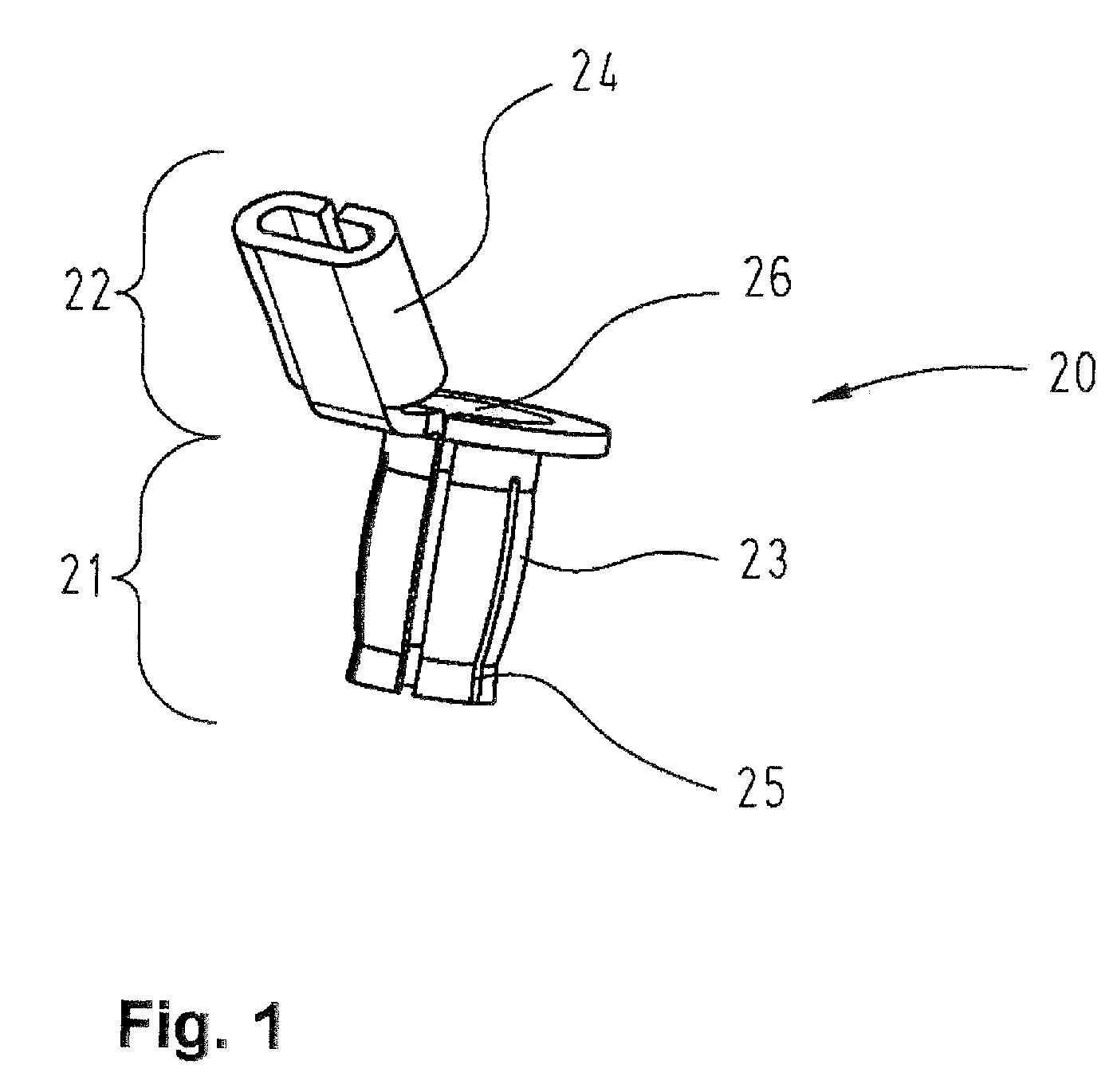
FIG. 1 shows a detailed three-dimensional view of an electric contact 20 with a contact region 21 and a terminal region 22 that is realized in the form of a punched and rolled part.

This figure shows the sleeve-like contact region 21 that features a bulgy distention 23 in its center. Axial slots 25 extend from the end of the contact region 21 that is illustrated on the bottom in this figure to slightly beyond the end of the bulgy distention 23 that is illustrated on the top. After connecting an electric conductor 16, a termination 24 designed for crimping is provided with a housing 10 together with the terminal region 22 of the electric contact 20. A first opening 26 of the contact region 21 that is illustrated on the top in this figure is not covered by the housing 10 in order to insert a clamping pin 7 such that a second opening 11 is formed in the housing.

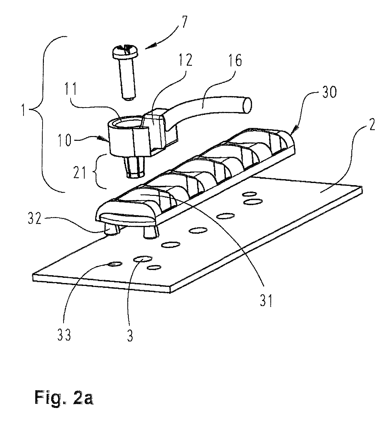
FIG. 2a shows the electric contact 20 provided with a potted housing 10 prior to the mounting on a printed circuit board 2. In ...


PUM


Abstract

In order to separably connect an electric conductor (16) to a printed circuit board (2), it is proposed to insert a connecting element (1) into an opening (3) in the printed circuit board (2). In this case, a sleeve-like contact region (21) of the connecting element (1) is clamped against the inner surface (4) of the opening (3) by means of a clamping pin (7).

Description

BACKGROUND OF THE INVENTION1. Field of the InventionThe invention pertains to an electric connecting element consisting of an is electric contact, a housing and a clamping pin for separably mounting an electric conductor on an opening of a printed circuit board.2. Description of the Related ArtConnecting elements of this type are required for contacting an electric conductor at any location on a printed circuit board. In this case, optimal electric contacting between the printed circuit board and the connecting element needs to be ensured by means of a flawless mechanical seat of the connecting element on the printed circuit board.U.S. Pat. No. 7,290,344 B2 discloses a method for connecting an electric conductor to a metal plate, wherein a cable lug radially expands a sleeve in a hole in the metal due to a screwed connection and thusly produces an electric connection.DE 197 49 890 C1 discloses an electronic contact element that is provided with a central bore and axial slots on the ...

Claims


Application Information

Patent Timeline
Patent Type & Authority Patents(United States)
IPC IPC(8): H01R12/00H01R12/55H01R12/58H01R12/71
CPCH01R11/28H01R12/585H01R12/7011H01R13/50H01R13/502H01R43/16
Inventor SCHWETTMANN, HARTMUTNASS, ANDREASSCHNIEDER, STEFAN
Owner HARTING ELECTRIC GMBH & CO KG
Why Eureka
Try Eureka