
Device and method for assisting in flexor tendon repair and rehabilitation

a technology for flexor tendon and flexor tendon, which is applied in the field of assisting in flexor tendon repair and rehabilitation, can solve the problems of unpredictable outcome and difficult tendon repair surgery at this site, and achieve the effects of minimizing the possibility of tendon rupture, smooth glide into and out, and minimizing the damage to the repair si

Active Publication Date: 2011-12-13
TOBY ORTHOPAEDICS
View PDF19 Cites 24 Cited by
  • Summary
  • Abstract
  • Description
  • Claims
  • Application Information

AI Technical Summary

Benefits of technology

[0017]It is well known that the prognosis for a tendon repair is more predictable and generally better when the laceration to the tendon has taken place in a portion of the tendon that is not located within the flexor tendon sheath; for example, in the palm or the forearm. Conversely, the portion of the tendon within the flexor tendon sheath has acquired the name, “no man's land,” because tendon repair surgery at this site can be very challenging and often has an unpredictable outcome. It is within this particular area, i.e., “no man's land,” that the present invention has its preferred application.
[0018]It is an object of the present invention to provide a device and method that will facilitate the manipulation of a severed tendon end during surgery from its retracted position to a desired location through the several pulleys of the flexor tendon sheath.
[0019]Once the tendon is repaired using an accepted suture and repair technique, a significant amount of destructive rubbing and friction on the repair site will result as the repair site glides through and contacts the edges of the pulleys of the flexor tendon sheath. Therefore, it is a further object of the present invention to provide a device and method that will minimize the destructive rubbing and friction that a relatively bulky repair site experiences while passing or gliding through the tight pulleys of the flexor tendon sheath during rehabilitation.
[0020]Accordingly, one embodiment of the present invention is a non-implantable device comprised of a hollow member, preferably shaped as a partial funnel and / or cone, having an inner and outer surface, a flared mouth, and an elongated handle, preferably attached to the flared mouth, for ease of manipulation. In a preferred embodiment of the present invention, the hollow member is further comprised of a shaft and an apical end. During a flexor tendon repair procedure involving a severed tendon, the flared mouth of the hollow member is introduced into the pulley and placed directly adjacent to the free end of the tendon. The flared mouth of the hollow member creates a wider, artificial pulley edge that permits the inflamed tendon end to traverse the edge of the pulley while minimizing contact with the pulley as well as potential damage to the tendon. With the non-implantable device, an inflamed and / or engorged tendon end, that otherwise may not easily pass through the edge of a pulley, can be placed into the flared mouth of the device and gently compressed through the shaft and apical end of the device, wherein the tendon end will be simultaneously squeezed into the pulley in a smooth and non-damaging manner. The process is analogous to that of a shoehorn providing a smooth and gradual entry of a large heel into and through a sharp and tight edge of a shoe.
[0024]In circumstances wherein the repair site must glide into and out of a single pulley edge during finger flexion, the surgeon can place the apical end of the implantable device into the pulley edge so that the flared mouth of the device sits directly adjacent to the repair site, thus allowing the repair site to smoothly glide into and out of the implantable device and corresponding pulley. With the implantable device in place, the surgeon can insure that during finger flexion a bulky repair site will smoothly glide in and out of one or more pulleys without abutting the pulley edges, thus minimizing the damage caused to the repair site and minimizing the possibility of tendon rupture. With improved tendon gliding, the implantable device also minimizes the formation of adhesions around the tendon and improves finger motion; the need for a future secondary operation to remove adhesions around a repair site is also obviated.
[0025]In another embodiment, wherein the repair site must glide partially into a more proximal pulley and partially into a more distal pulley during flexion, the surgeon can insert one implantable device into the edge of the pulley proximally adjacent to the repair site, and another implantable device into the edge of the pulley distally adjacent to the repair site. The respective flared mouths of each device would each face the repair site as well as one another. Utilizing the foregoing arrangement, the surgeon can ensure that a bulky repair site smoothly glides into and out of a proximal and distal pulley edge.

Problems solved by technology

Therefore, current studies (the majority of which are in vitro) do not account for the interaction and resulting friction between a repaired flexor tendon and its respective, tightly-fitting flexor tendon sheath.
Conversely, the portion of the tendon within the flexor tendon sheath has acquired the name, “no man's land,” because tendon repair surgery at this site can be very challenging and often has an unpredictable outcome.
Once the tendon is repaired using an accepted suture and repair technique, a significant amount of destructive rubbing and friction on the repair site will result as the repair site glides through and contacts the edges of the pulleys of the flexor tendon sheath.

Method used


Image

  • Device and method for assisting in flexor tendon repair and rehabilitation
  • Device and method for assisting in flexor tendon repair and rehabilitation
  • Device and method for assisting in flexor tendon repair and rehabilitation

Examples


Embodiment Construction

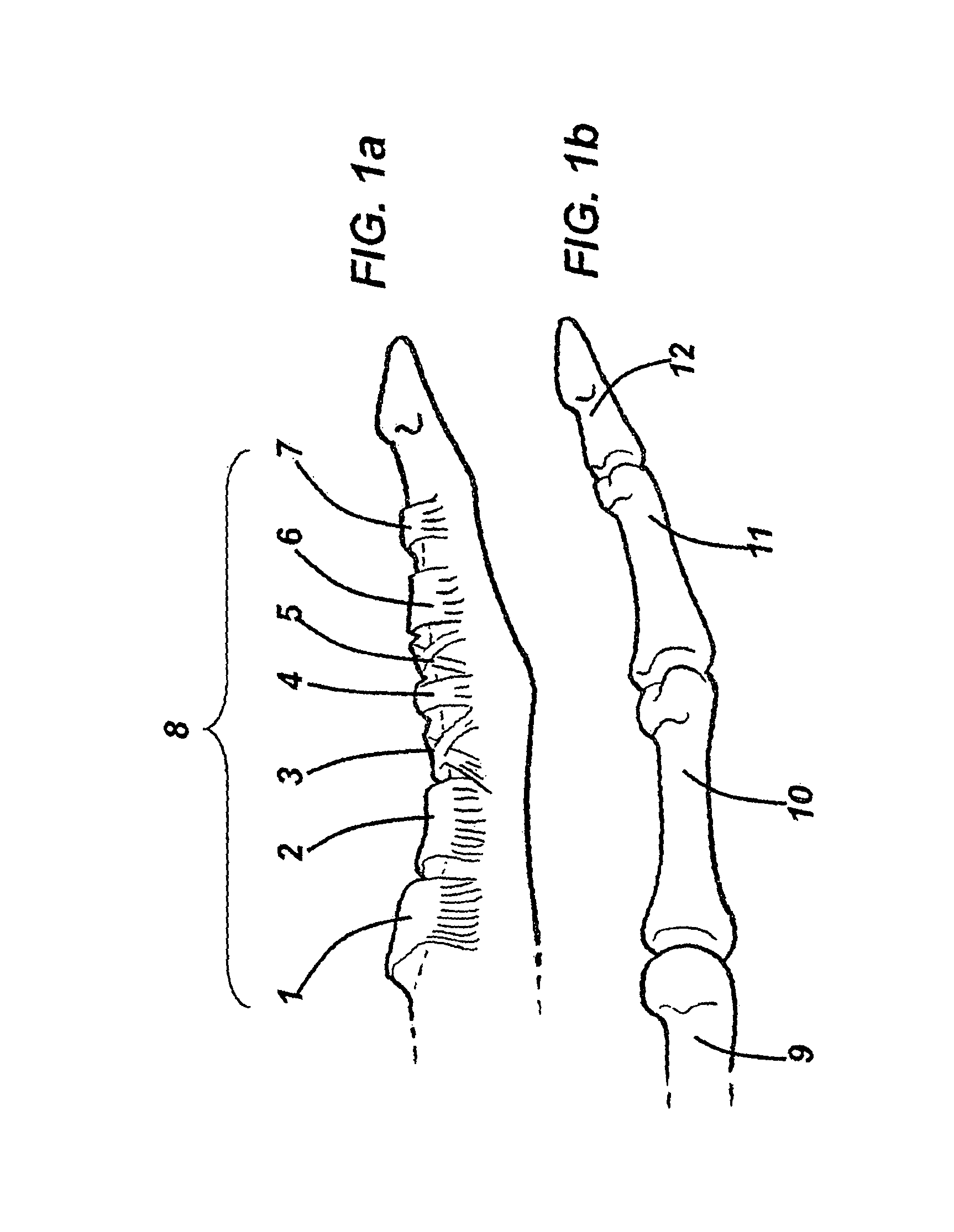
[0039]FIG. 1a illustrates the specific segments of a flexor tendon sheath 8 that are critical for the proper function and effectuation of finger flexion. FIG. 1b further illustrates a finger, its skeleton, and the different finger joints associated with the flexor tendon sheath 8. Pursuant to proper anatomic nomenclature, wherein structures closer to the head are referred to as “proximal” and structures further from the head are referred to as “distal,”FIG. 1b depicts the metacarpal 9, the proximal phalanx 10, the middle phalanx 11, and the distal phalanx 12.

[0040]As depicted in FIG. 1a, the flexor tendon sheath 8 is a continuous pulley system starting with the most proximal pulley 1 and finishing with the most distal pulley 7. The system of pulleys that comprises the flexor tendon sheath 8 has identifiable reinforced segments which form and correspond to each individual pulley, 1,2,3,4,5,6 and 7.

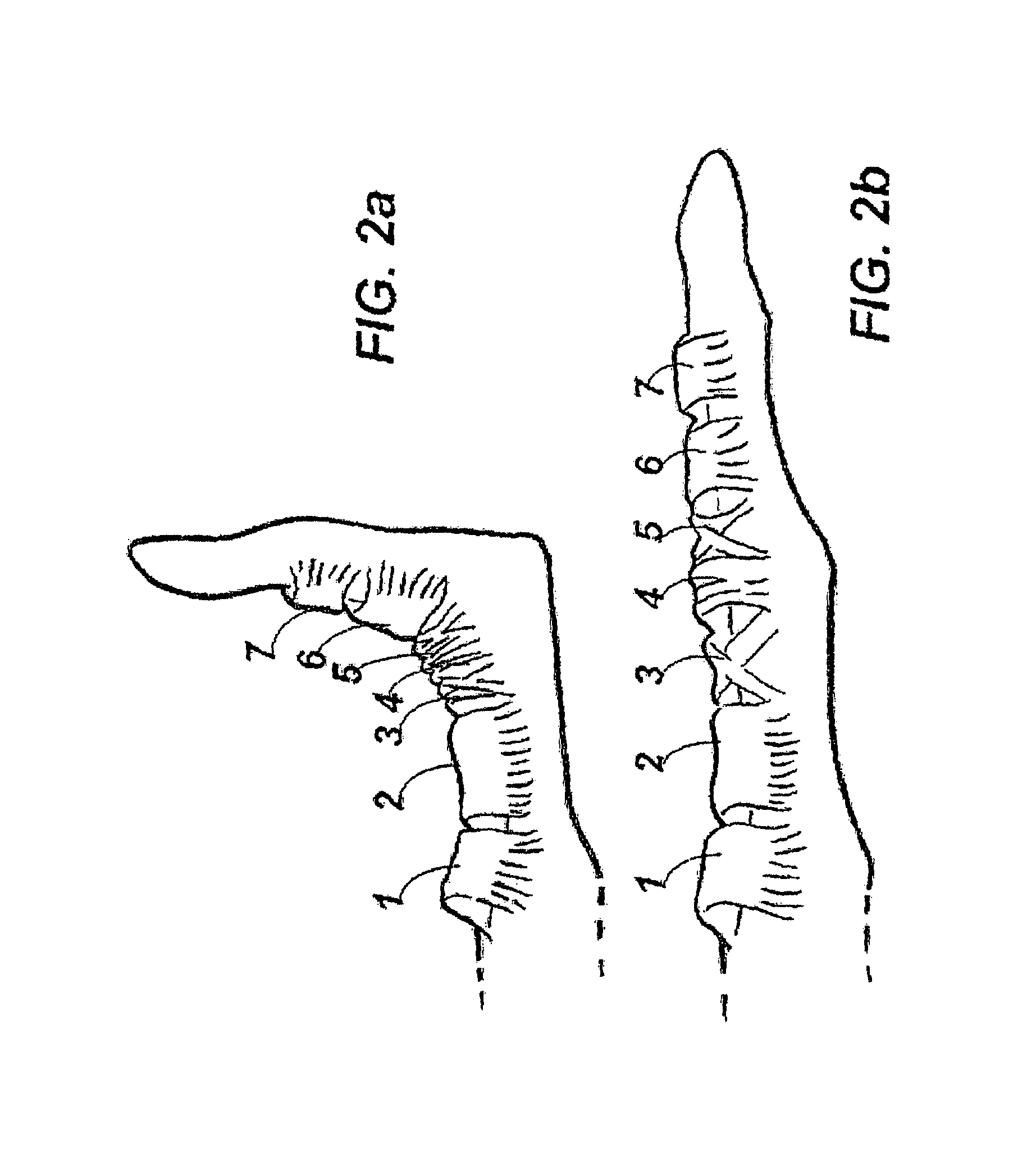
[0041]As illustrated in FIGS. 2a and 2b, the criss-cross arrangement of fibres in pulle...


PUM


Abstract

A surgical device and method used to assist in the surgical repair and rehabilitation of damaged and / or severed tendons. In one embodiment of the present invention, the device includes a hollow member, preferably shaped as a partial funnel and / or cone, having an inner and outer surface, a flared mouth, a shaft, and an apical end. In another embodiment, the device includes a hollow member, preferably shaped as funnel or barrel cut in half along its longitudinal axis, having an inner and outer surface, two flared mouths, and a shaft. The device may further include a thin, elongated handle for ease of manipulation, and can be implantable or non-implantable. The present invention further discloses a method of passing a severed flexor tendon and / or repair site through the edge of a pulley in the flexor tendon sheath, wherein the hollow member of the device disclosed in the present invention is introduced into the edge of a flexor tendon sheath's pulley and a severed tendon end and / or repair site is passed through the flared mouth of the device and is gently compressed through the shaft and apical end of the device so that the tendon end or repair site can be simultaneously squeezed into the pulley in a smooth and non-damaging manner.

Description

CROSS REFERENCES TO RELATED APPLICATIONS[0001]This application claims the benefit under 35 U.S.C. §119(e) of U.S. Provisional Application No. 60 / 955,729, filed on Aug. 14, 2007, the complete disclosure of which is incorporated herein by reference in its entirety.FIELD OF THE INVENTION[0002]The invention relates to a surgical device and method used to assist in the surgical repair and rehabilitation of damaged and / or severed tendons.BACKGROUND OF THE INVENTION[0003]In the hand, the fingers are moved by flexor and extensor tendons arising from muscles in the forearm. Inspection of the flexor tendon mechanism reveals three main components: 1) the skeleton, including the bones and the articulations or joints between the bones; 2) a tunnel or pulley system for the tendon; and 3) the tendon itself.[0004]In each finger, two flexor tendons work to flex the proximal and distal interphalangeal joints, namely the flexor digitorum superficialis and the flexor digitorum profundis respectively.[0...

Claims


Application Information

Patent Timeline
Patent Type & Authority Patents(United States)
IPC IPC(8): A61B17/04
CPCA61B17/1146A61B17/0218A61B17/04A61F2/0811A61B2019/4836A61F2/0805A61B2090/0807A61B2017/00004
Inventor GONZALEZ-HERNANDEZ, EDUARDO
Owner TOBY ORTHOPAEDICS
Learn More