Windowed flexor tendon sheath retractor & dilator

a technology of flexor tendon and sheath, which is applied in the surgical field, can solve the problems of unpredictable outcomes and difficult proportion of flexor tendon within the sheath, and achieve the effects of facilitating the manipulation of a severed tendon, and improving the overall outcome of the procedur

Inactive Publication Date: 2011-05-12
STEFFEN DENNIS L
View PDF5 Cites 3 Cited by
  • Summary
  • Abstract
  • Description
  • Claims
  • Application Information

AI Technical Summary

Benefits of technology

[0008]The invention provides a device and method for flexor tendon repair. The majority of publications addressing flexor tendon repair focus on the strength of repairs regarding various suture techniques. It is well known that the prognosis for a tendon repair is more predictable and generally better when the laceration to the tendon has taken place in a portion of the tendon that is not located within the flexor tendon sheath; for example, in the palm or the forearm. The portion of the tendon within the flexor tendon sheath can be difficult with unpredictable outcomes. It is the goal of the present invention to provide a device and method that will facilitate the manipulation of a severed tendon free end during surgery and greatly improve the overall outcome of the procedure.
[0009]In one embodiment of the present invention is a device comprised of a conical shaped feature (Retractor), having an inner and outer surface, a flared proximal end and a tapered distal tip, a handle is joined to the proximal end with a Dilator similar in proportion and shape of the Retractor is located at the opposite end. In a preferred embodiment of the present invention, the Retractor is further comprised of two openings. These two openings act as windows for improved visibility of the tendon during the procedure. The two windows also reduce the surface area of the inner surface thus reducing drag on the tendon as it is pulled back into the sheathing and pulley system. During a flexor tendon repair procedure involving a severed tendon, the distal tip of the Retractor is introduced into the pulley and placed directly adjacent to the free end of the tendon. The proximal flared end of the Retractor acts as a guide to aid in the introduction of the free end of the tendon back into the sheathing and pulley system. When an inflamed and / or engorged tendon end, that otherwise may not easily pass through the edge of a pulley, can be placed into the proximal flared end of the device and gently compressed wherein the tendon end will be simultaneously squeezed into the pulley in a gentler manner.

Problems solved by technology

The portion of the tendon within the flexor tendon sheath can be difficult with unpredictable outcomes.

Method used


Image

  • Windowed flexor tendon sheath retractor & dilator
  • Windowed flexor tendon sheath retractor & dilator
  • Windowed flexor tendon sheath retractor & dilator

Examples


Embodiment Construction

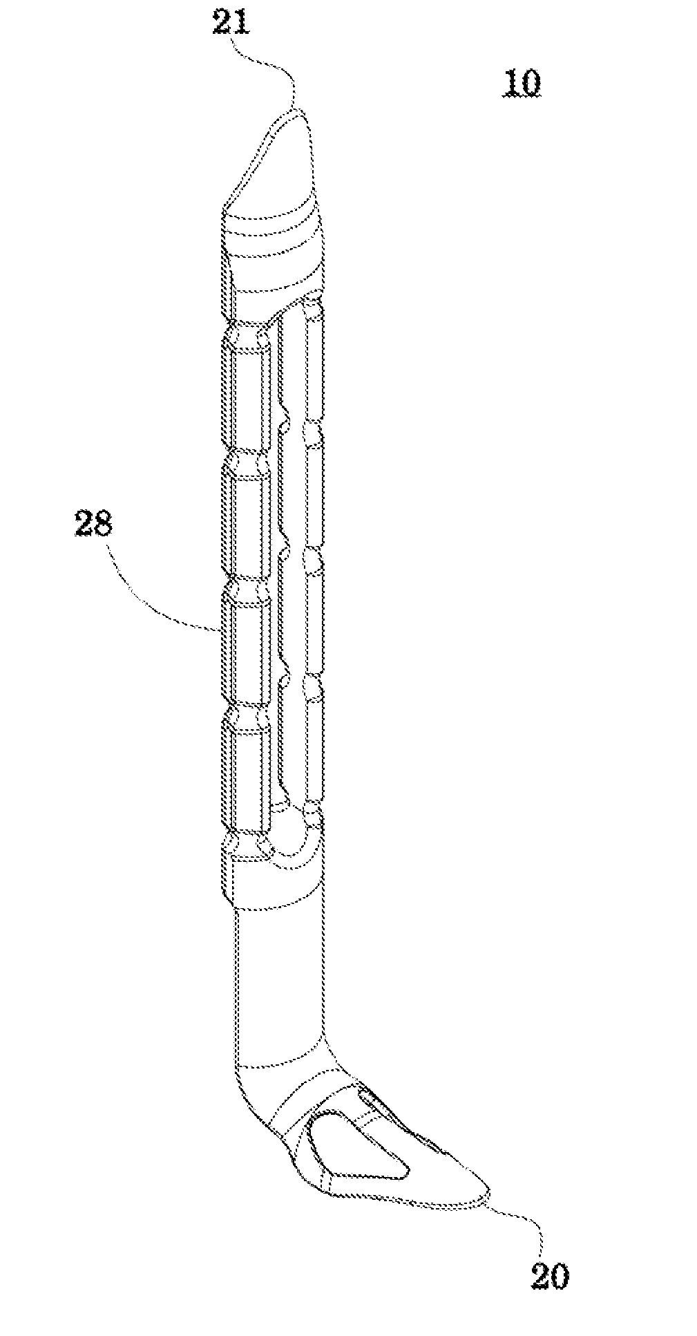
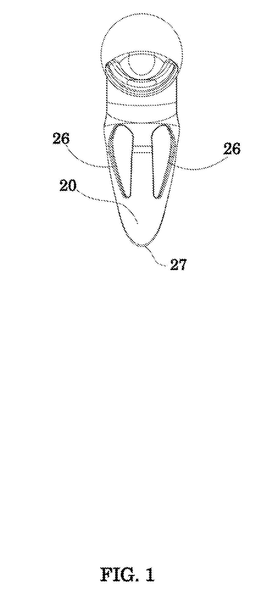
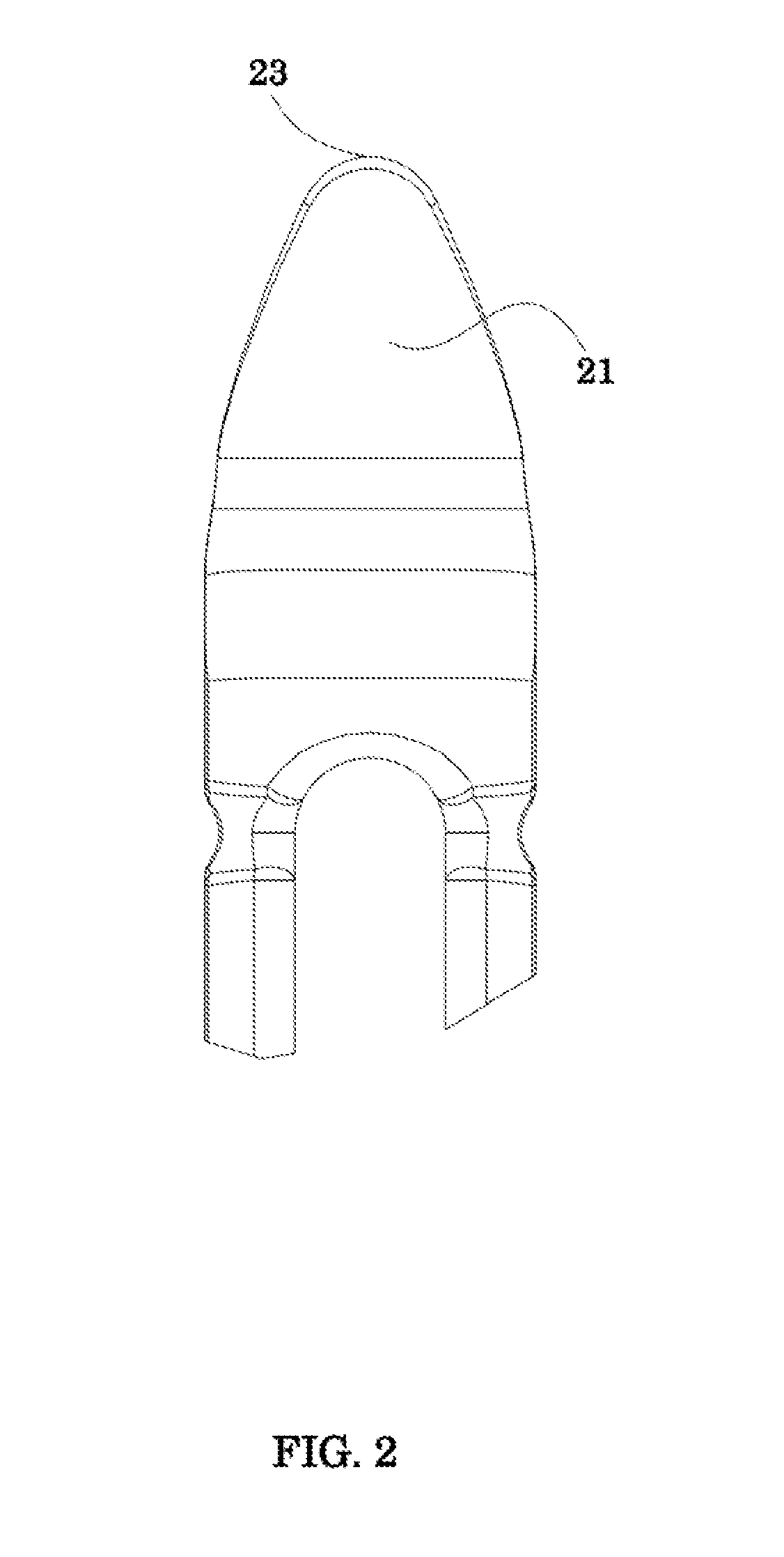
[0018]A flexor tendon sheath retractor & dilator embodying the principles of the invention is provided.

[0019]Before any embodiments of the invention are explained in detail, it is to be understood that the invention is not limited in its application to the details of the structure and function set forth in the following description or illustrated in the appended drawings. The invention is capable of other embodiments and of being practiced or of being carried out in various ways. Also, it is to be understood that the phraseology and terminology used herein is for the purpose of description and should not be regarded as limiting. The use of “including,”“comprising,” or “having” and variations thereof herein is meant to encompass the items listed thereafter and equivalents thereof as well as additional items. “Comprising” also encompasses the terms “consisting of” and “consisting essentially of.” The use of “consisting essentially of” means, e.g., that a method may include additional ...


PUM


Abstract

A surgical device and method used to assist in the surgical repair of damaged and / or severed tendons. In the present invention, the device is comprised of a distal conical member, having an inner and outer surface, a tapered tip, a rounded end, and windowed openings on either side of axial centerline passing through the inner and outer surfaces. In the same embodiment, the device is comprised of a proximal concave convex member with an inner and outer surface, a tapered tip, and a rounded end, tapering both in width and thickness to the tip. The present invention further discloses a method of passing a severed flexor tendon through the tendon sheathing to the repair site aiding in the passage of the severed tendon through the edges of the pulleys in the flexor tendon sheath, wherein the distal conical member of the device disclosed in the present invention is introduced into the edge of a flexor tendon sheath's pulley and a severed tendon end is passed along the inner surface of the conical member allowing the tendon to be reintroduced into the sheathing with minimal trauma. The present invention further discloses a method of dilation of the pulleys in the flexor tendon sheath, wherein the proximal concave convex member of the device disclosed in the present invention is introduced into the edge of a flexor tendon sheath's pulley to a desire depth and left in place until the desired amount of dilation is achieved the tendon is then introduced back into the sheathing utilizing the afore described method.

Description

CROSS REFERENCES TO RELATED APPLICATIONS[0001]This application claims the benefit under 35 U.S.C. §119(e) of U.S. Provisional Application No. 61 / 259,665, filed on Nov. 10, 2009, the complete disclosure of which is incorporated herein by reference in its entirety.FIELD OF THE INVENTION[0002]The present invention relates to a surgical device and method used to assist in the surgical repair of damaged and / or severed tendons.INTRODUCTION[0003]In the hand, the fingers are moved by flexor and extensor tendons arising from muscles in the forearm. The flexor tendon mechanism reveals three main components: 1) the skeleton, including the bones and the articulations or joints between the bones; 2) a tunnel or pulley system for the tendon; and 3) the tendon itself.[0004]There are two flexor tendons in each finger which work to flex the proximal and distal interphalangeal joints, namely the flexor digitorum superficialis and the flexor digitorum profundus respectively.[0005]A fibrous sheath hold...

Claims


Application Information

Patent Timeline
Patent Type & Authority Applications(United States)
IPC IPC(8): A61B17/56
CPCA61B17/02
Inventor STEFFEN, DENNIS L.
Owner STEFFEN DENNIS L
Why Eureka
Try Eureka