Modelling and simulation method

a simulation method and model technology, applied in the field of model and simulation method, can solve the problems of complex system in its entirety testing, high cost, and high cost, and achieve the effect of reducing the cost of rtl

Active Publication Date: 2011-12-20
SIEMENS PROD LIFECYCLE MANAGEMENT SOFTWARE INC
View PDF14 Cites 9 Cited by
  • Summary
  • Abstract
  • Description
  • Claims
  • Application Information

AI Technical Summary

Problems solved by technology

This is a clear disadvantage of the prior art simulation methodology described above.
Furthermore, testing a complex system in its entirety when all its component units are described at RTL is likely to be very time consuming both in the creation of test data (known as a testbench) and in simulation.
However, such testing requires more effort to be expended in analysing simulation results.
However, two severe problems remain.
First, true system level modelling is still difficult to achieve because not enough higher level features are native to the languages.
Second, behavioural level models cannot be connected to RTL models so no direct comparison can be made between the behavioural models and the RTL models and the validation of the behavioural models does not necessarily imply equivalent validation of the RTL models.
Creating translators manually between the levels has proved to be a task at least as complex and error prone as creating the models themselves.
Some of the problems of the prior art described above arise because of the differing abstraction levels used to model hardware systems, and the difficulty of modelling differing levels of abstraction concurrently.
However, automatically generating and implementing these conversions has not been successfully carried out.
Indeed, problems with the VHDL+ language have resulted in it being withdrawn from general availability, and an IEEE project to standardise the language has been withdrawn.
Therefore, although VHDL+ sought to overcome the problems associated with simulation at high levels, and also to overcome the problems of multi-level modelling, there is no known method of automatically and accurately simulating a system when parts of that system are specified at a high level (e.g. system level) and parts are specified at a lower level (e.g. RTL).

Method used


Image

  • Modelling and simulation method
  • Modelling and simulation method
  • Modelling and simulation method

Examples


Embodiment Construction

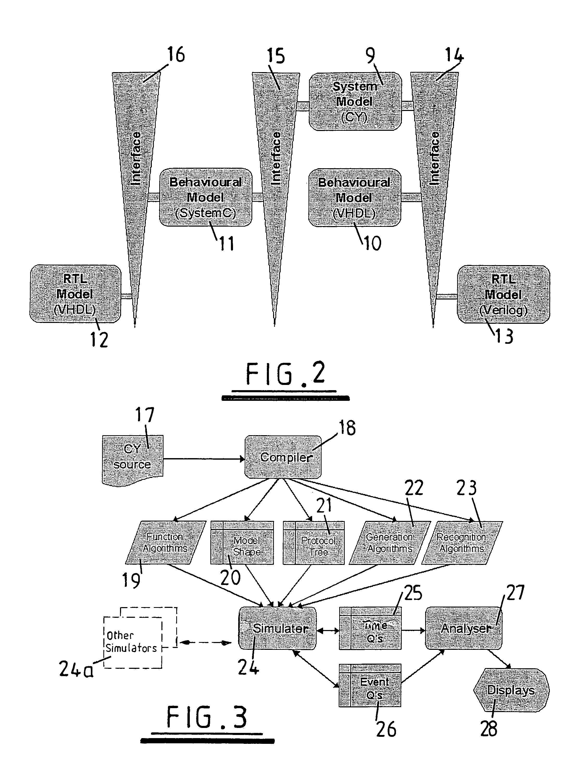
[0046]Appendix 1 and Appendix 2 show CY source code for illustrative examples of the invention; and

[0047]Appendix 3 shows C++ code created from the CY source code of Appendix 1.

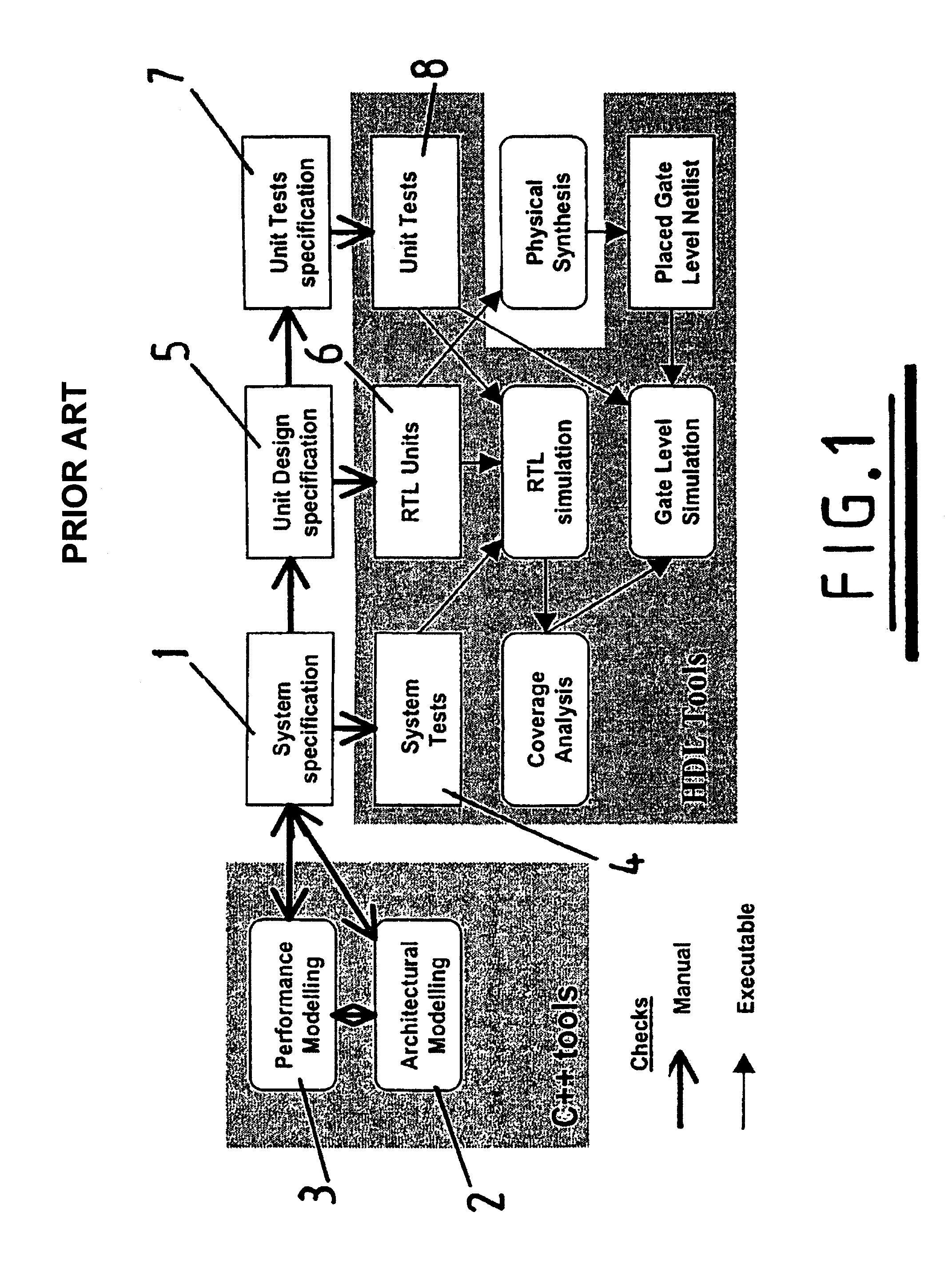
[0048]Referring to FIG. 1, there is illustrated a modelling process known from the prior art. Initially a system specification 1 is created in a natural language such as English. Architectural modelling 2 and performance modelling 3 are carried out using a high level programming language such as C++. During this modelling phase the system specification 1 may be amended in the light of results obtained from the modelling process 2, 3. When the system specification 1 has been finalised system tests 4 are created from the specification 1. Such tests are usually specified at Register Transfer Level (RTL) so that they can be run on the full System Model. A Unit design specification 5 is also created from the system specification 1. This specification details of units which are to make up the system and is again wr...


PUM


Abstract

A method for simulating behavior of first and second interrelated components within a system. The method comprises modelling behavior of said first and second components using first and second functional specifications; simulating behavior of said first and second components in predetermined circumstances by instantiating at least one first entity within a hierarchy of interrelated entities; and instantiating at least one further entity in response to the or each instantiated first entity. The or each further entity is selected by a simulation system on the basis of its hierarchical relationship with the at least one first entity.

Description

COMPUTER PROGRAM LISTING APPENDIX[0001]The computer program listing appendix is submitted as an ASCII text file named “Appendices_79218-01.txt,” created on Oct. 3, 2011, 15.1 KB, which is incorporated by reference herein.BACKGROUND AND SUMMARY[0002]The present invention relates to a modelling and simulation method.[0003]It is well known to build a model of a system and to use a simulation process to show the behaviour of that model in various circumstances. Many modelling methodologies are well known, and the methodology selected for any particular application will be determined by the requirements of that application.[0004]It is well known to model computer hardware systems prior to fabrication. Such modelling often includes applying a simulation process to a model to ensure that the modelled system exhibits the required behaviour. Once the simulation process has determined that the modelled system exhibits the required behaviour it is known that building an implementation which is...

Claims


Application Information

Patent Timeline
Patent Type & Authority Patents(United States)
IPC IPC(8): G06F9/44G06F13/10G06F13/12G06F9/45G06F17/50
CPCG06F17/5022G06F30/33G06F11/3664G06F8/20G06F11/3457G06F11/323G06F30/367
Inventor HODGSON, STEVENPOLYCHRONOPOULOS, JASON SOTIRISJONES, CHRISTOPHERSHAAR, ZAKWANHASHMI, MUHAMMED MUTAHER KAMALTHEOBALD, LENHUGHES, WILFRED BARRY
Owner SIEMENS PROD LIFECYCLE MANAGEMENT SOFTWARE INC
Why Eureka
Try Eureka