Side under spoiler mounting structure

a technology for mounting structures and spoilers, which is applied in washstands, roofs, lighting support devices, etc., can solve the problems that brackets and side under spoilers cannot maintain their ability to be joined to the vehicle body for a long tim

Active Publication Date: 2011-12-27
HONDA ACCESS CORP
View PDF18 Cites 24 Cited by
  • Summary
  • Abstract
  • Description
  • Claims
  • Application Information

AI Technical Summary

Benefits of technology

[0008]The present invention was made in view of such circumstances, and an object of the present invention is to provide a side under spoiler mounting structure that can mount a side under spoiler made of a different material from that of a vehicle body to the vehicle body more firmly, and that can allow a bracket and a side under spoiler after mounted to maintain, for a long term, their ability to be joined to the vehicle body.
[0010]According to the first aspect of the invention, since the lower portion of the vehicle and the bracket have an equal level of thermal expansion or thermal contraction, a bonded surface of the bracket can be prevented from losing the bond with the lower portion of the vehicle due to any deformation difference that may be caused if the bracket and the lower portion of the vehicle have different thermal expansion coefficients. The side under spoiler, which is engaged with the bracket, can be kept supported on the bracket even if the side under spoiler thermally expands or thermally contracts, so the side under spoiler that is made of a different material from that of the vehicle body can be more firmly mounted on the vehicle body. Hence, the bracket and the side under spoiler after mounted can maintain their ability to be joined to the vehicle body for a long term.

Problems solved by technology

Hence, these side under spoiler mounting structures are at a risk that the double-stick tape that bonds the bracket to the vehicle body might peel off due to deformation of the bracket and the vehicle body caused by a difference in how they thermally expand when the temperatures of the vehicle body, the bracket, and side under spoiler rise as the ambient temperature changes, raising a problem that the bracket and the side under spoiler cannot maintain their ability to be joined to the vehicle body for a long term.

Method used


Image

  • Side under spoiler mounting structure
  • Side under spoiler mounting structure
  • Side under spoiler mounting structure

Examples


Embodiment Construction

[0034]One embodiment of the present invention will be specifically described below with reference to the drawing.

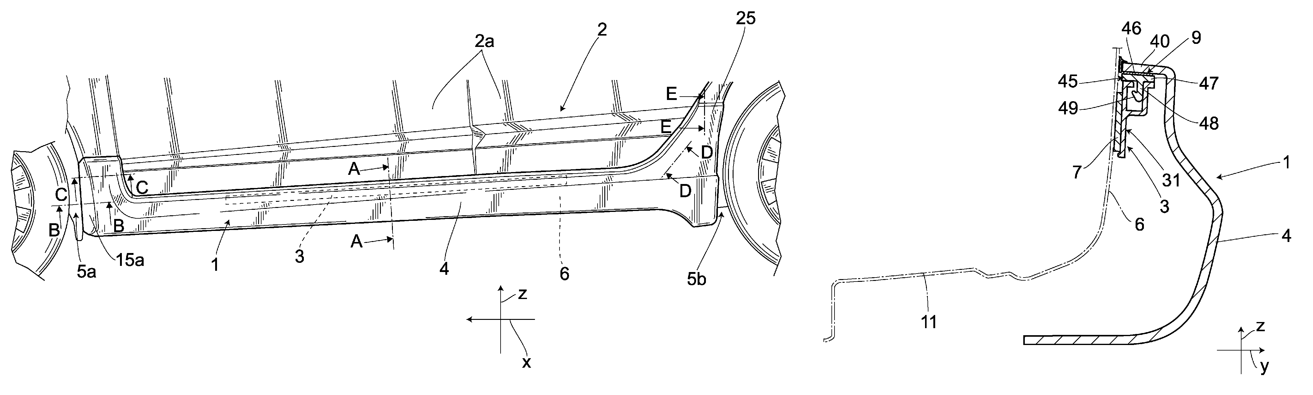
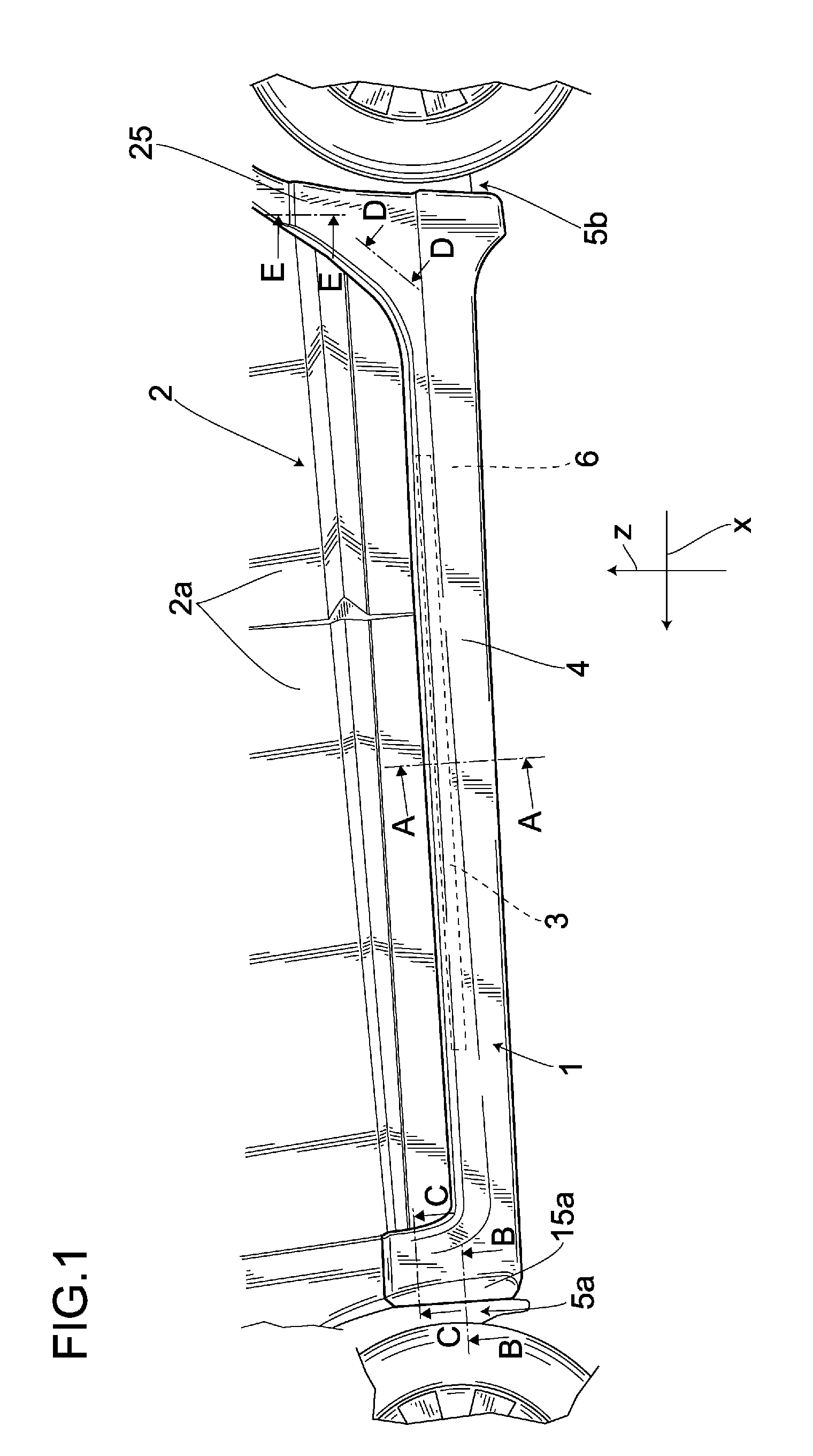
[0035]In FIG. 1, the reference numeral “1” denotes a side under spoiler mounting structure provided on a side surface of a vehicle body 2. The side under spoiler mounting structure 1 includes a bracket 3 and a side under spoiler 4.

[0036]In a practical sense, the side under spoiler mounting structure 1 may be provided on a frame portion 6 at the lower portion of doors 2a (this frame portion 6 will hereinafter be referred to as vehicle lower portion) between a front wheel house 5a and a rear wheel house 5b, such that the bracket 3 and the side under spoiler 4 extends along a vehicle front-rear direction x.

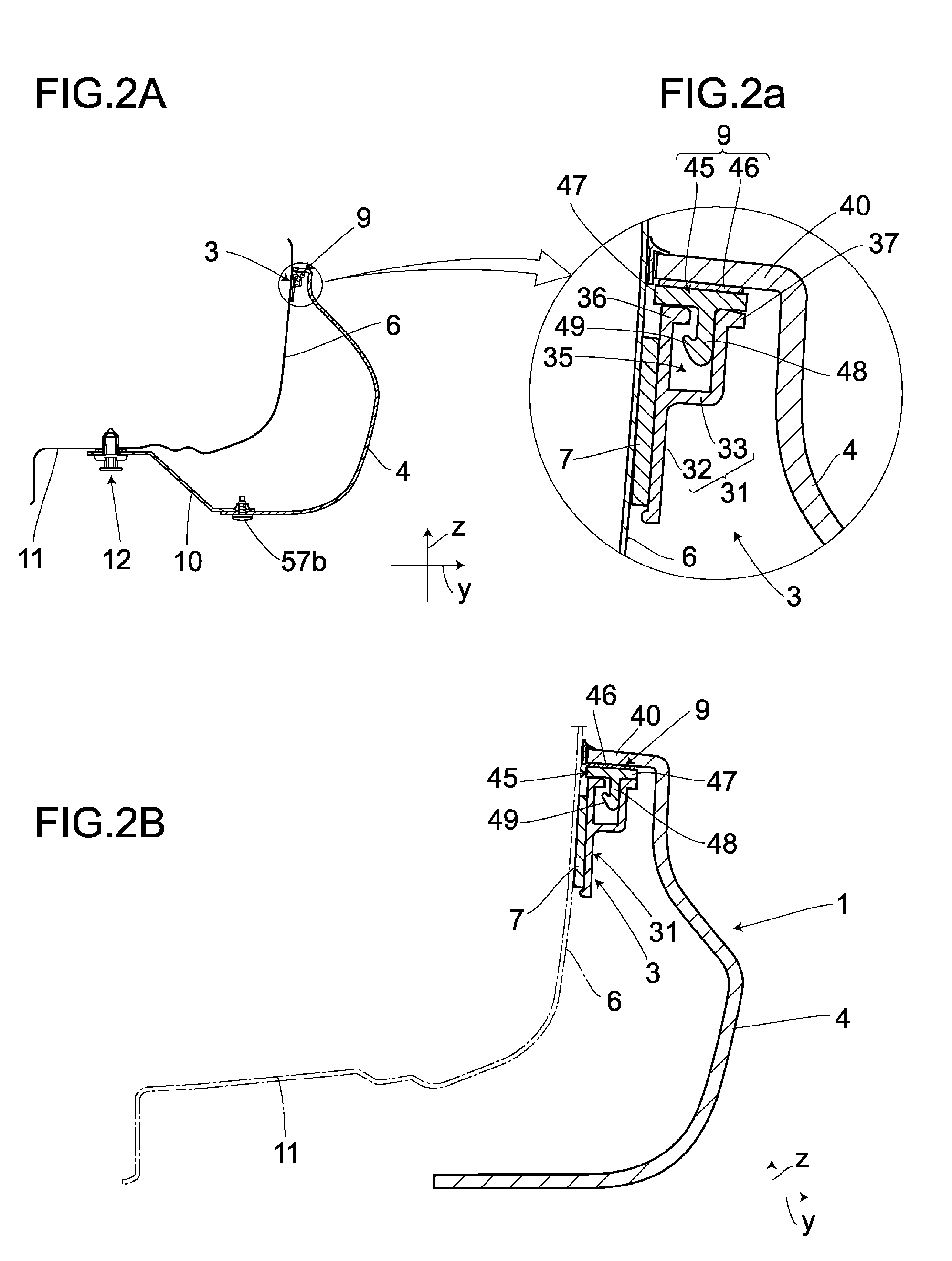
[0037]First, how the side under spoiler 4 is mounted on the vehicle lower portion 6 will be briefly explained. As shown in FIG. 2(A), which shows a vertical cross section taken between the positions of the symbols A and A of FIG. 1 that are substantially along a vehicle ve...


PUM


Abstract

Because a vehicle lower portion 6 and a bracket 3 have an equal level of thermal expansion or thermal contraction, a bonded surface of the bracket 3 can be prevented from losing the bond with the vehicle lower portion 6 due to any deformation difference that might be caused if they have different thermal expansion coefficients. A side under spoiler 4 can be kept supported on the bracket 3 even if the side under spoiler 4 thermally expands or thermally contracts, and hence the side under spoiler 4 made of a different material from that of a vehicle body 2 can be more securely mounted on the vehicle body 2. The bracket 3 and the side under spoiler 4 after mounted can maintain their ability to be joined to the vehicle body 2 for a long term.

Description

BACKGROUND OF THE INVENTION[0001]1. Field of the Invention[0002]The present invention relates to a side under spoiler mounting structure, which is suitable for use in mounting a side under spoiler, which extends in the front-rear direction of a vehicle body, to a side surface of the vehicle body.[0003]2. Description of the Related Art[0004]There has conventionally been known a vehicle trim piece (side under spoiler mounting structure) that includes a lengthy base that is bonded to a vehicle body with a double-stick tape, a decorative hollow cover (hereinafter referred to simply as cover) that is flexible and extends along the base, and a means provided on the cover and the base for joining the cover to the base in a snap-on manner (see, e.g., Japanese Patent Publication No. 3362848).[0005]There has also been known a side under spoiler mounting structure embodied by a bracket that is lengthy in the front-rear direction of a vehicle body and bonded to the vehicle body with a double-st...

Claims


Application Information

Patent Timeline
Patent Type & Authority Patents(United States)
IPC IPC(8): B60R13/00
CPCB60R13/04B62D25/2036B62D29/048B60R2013/046B62D35/008
Inventor YANAGIDA, TAKAYUKIMISONOU, YOSHIMASATAMAI, HIDEOMI
Owner HONDA ACCESS CORP
Why Eureka
Try Eureka