Vehicle seat

a headrest and vehicle seat technology, applied in the field of vehicle seat headrests, can solve the problems of long rotation radius of the headrest, seat back interference with inability to achieve so as to increase the space required for the the effect of smooth rotation of the headres

Inactive Publication Date: 2011-12-27
TS TECH CO LTD
View PDF6 Cites 21 Cited by
  • Summary
  • Abstract
  • Description
  • Claims
  • Application Information

AI Technical Summary

Benefits of technology

[0005]It is an object of the present invention to provide a vehicle seat in which a seat back does not interfere with rotation of a headrest when the headrest is rotated (when the headrest is accommodated).
[0006]It is another object of the invention to provide a vehicle seat in which a space required for rotating the headrest can be reduced in size.

Problems solved by technology

According to a conventional apparatus shown in FIG. 6, a headrest rotates around a horizontal rod C, but since the horizontal rod C is located inside a seat back, the seat back interferes with rotation of the headrest, and smooth rotation of the headrest can not be expected.
Further, since the horizontal rod C is located inside the seat back, there is a drawback that a rotation radius of the headrest becomes long and a space required for rotation of the headrest is increased.

Method used


Image

  • Vehicle seat
  • Vehicle seat
  • Vehicle seat

Examples


Embodiment Construction

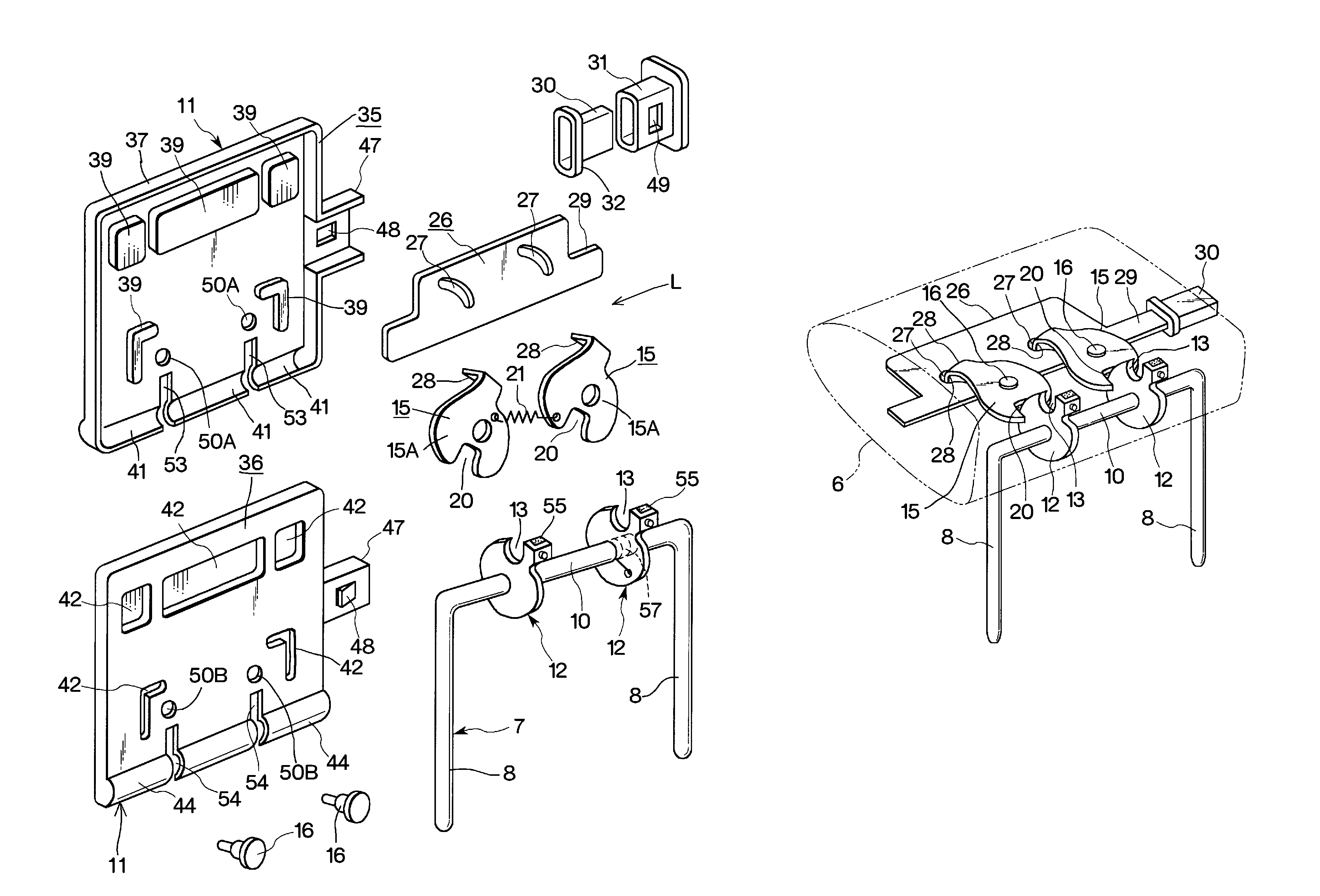
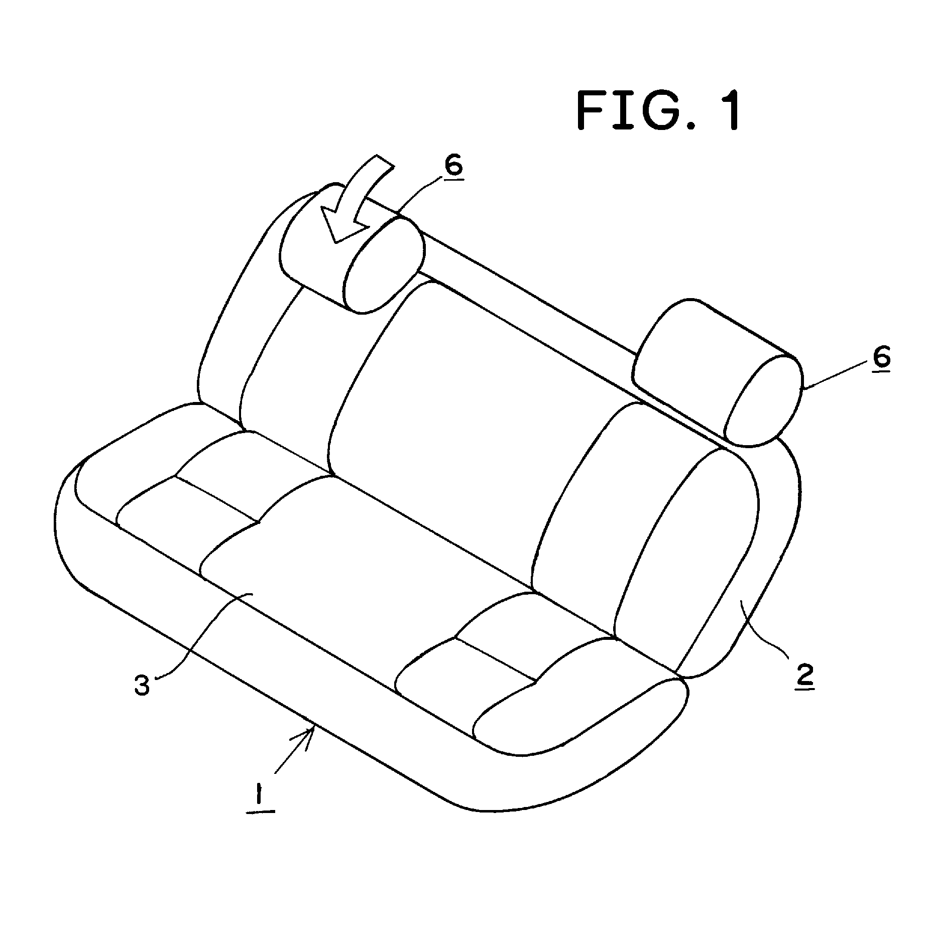
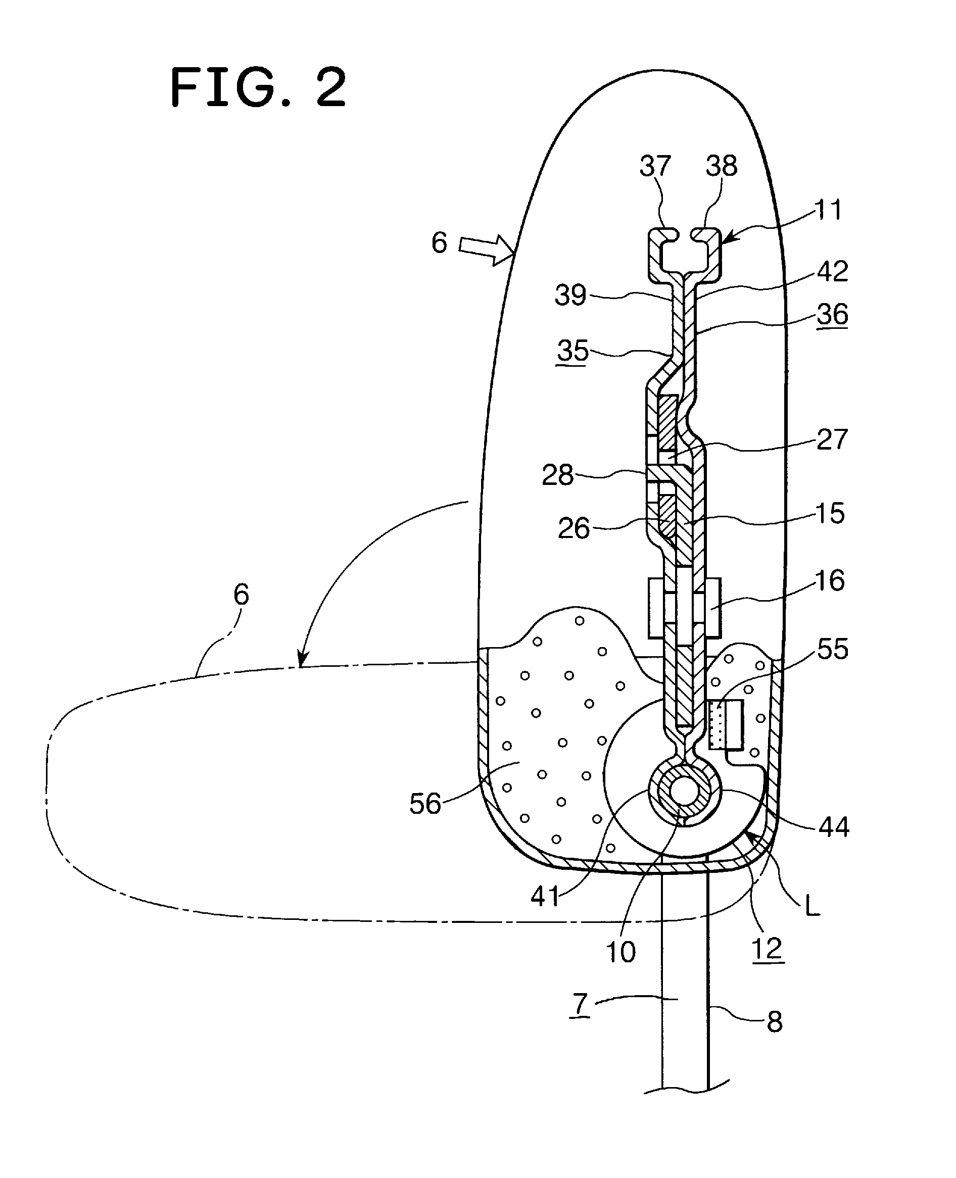
[0013]An embodiment of the present invention will be explained with reference to the drawings. A vehicle seat 1 of the invention includes a seat back 2, a seat bottom 3, and a headrest 6 provided on an upper portion of the seat back 2. The headrest 6 includes a reverse U-shaped support portion 7. The support portion 7 includes downwardly extending two pillars 8, and a horizontal section 10 which connects upper portions of the pillars 8 with each other. The pillars 8 are vertically slidably supported by the seat back 2.

[0014]A substantially square plate-like headrest frame 11 is provided inside of the headrest 6. The headrest frame 11 is surrounded by a cushion 56. The headrest frame 11 preferably includes a front plate 35 and a rear plate 36. The front plate 35 is formed at its peripheral edge with a front flange 37, and the rear plate 36 is formed at its peripheral edge with a rear flange 38.

[0015]A lower line of the front flange 37 is formed into a front arc mounting surface 41 wh...


PUM


Abstract

A vehicle seat comprises a seat back, a seat bottom, a headrest mounted on an upper portion of the seat back. The headrest includes a reverse U-shaped support section having downwardly extending two pillars and a horizontal section which connects upper portions of the pillars with each other. A lock plate is fixed to the horizontal section. A headrest frame is provided with an engagement disk which is changed over between a lock position where the engagement disk engages with the lock plate to disable the headrest to rotate about the horizontal section, and an unlock position where the engagement disk disengages from the lock plate to enable the headrest to rotate around the horizontal section.

Description

TECHNICAL FIELD[0001]The present invention relates to a headrest of a vehicle seat, and more particularly, to a mechanism for rotating the headrest between a use position and an accommodation position.BACKGROUND ART[0002]A conventional headrest provided on an upper portion of a seat back can rotate forward or backward. For example, an apparatus shown in FIG. 6 includes a base bracket A disposed inside of the seat back, and a pair of pillars B rotatably mounted on the bracket A. A headrest is fixed to upper portions of the pillars B.[0003]Patent document 1: JP 7(1995)-11951A (U)DISCLOSURE OF THE INVENTION[0004]According to a conventional apparatus shown in FIG. 6, a headrest rotates around a horizontal rod C, but since the horizontal rod C is located inside a seat back, the seat back interferes with rotation of the headrest, and smooth rotation of the headrest can not be expected. Further, since the horizontal rod C is located inside the seat back, there is a drawback that a rotation...

Claims


Application Information

Patent Timeline
Patent Type & Authority Patents(United States)
IPC IPC(8): A47C7/36
CPCB60N2/4841B60N2/4844B60N2/4858B60N2/841B60N2/844B60N2/859
Inventor YOSHIDA, MASAMI
Owner TS TECH CO LTD
Why Eureka
Try Eureka