
Connector with improved shielding in mating contact region

a technology of shielding and connecting rods, applied in the direction of coupling device connections, electrical equipment, coupling protective earth/shielding arrangements, etc., can solve the problems of large scale, faster and more complex functionalities, and small size of the electronic system

Active Publication Date: 2011-12-27
AMPHENOL CORP
View PDF13 Cites 121 Cited by
  • Summary
  • Abstract
  • Description
  • Claims
  • Application Information

AI Technical Summary

Problems solved by technology

Electronic systems have generally become smaller, faster and functionally more complex.

Method used


Image

  • Connector with improved shielding in mating contact region
  • Connector with improved shielding in mating contact region
  • Connector with improved shielding in mating contact region

Examples


Embodiment Construction

[0021]This invention is not limited in its application to the details of construction and the arrangement of components set forth in the following description or illustrated in the drawings. The invention is capable of other embodiments and of being practiced or of being carried out in various ways. Also, the phraseology and terminology used herein is for the purpose of description and should not be regarded as limiting. The use of “including,”“comprising,” or “having,”“containing,”“involving,” and variations thereof herein, is meant to encompass the items listed thereafter and equivalents thereof, as well as additional items.

[0022]As connectors become more dense and signal frequencies increase, there is a greater possibility of electrical noise being generated in the connector as a result of reflections caused by impedance mismatch or cross-talk between signal conductors. Therefore, electrical connectors are designed to control cross-talk between different signal paths and to contr...


PUM

PropertyMeasurementUnit
impedanceaaaaaaaaaa
impedanceaaaaaaaaaa
surface resistivityaaaaaaaaaa

Abstract

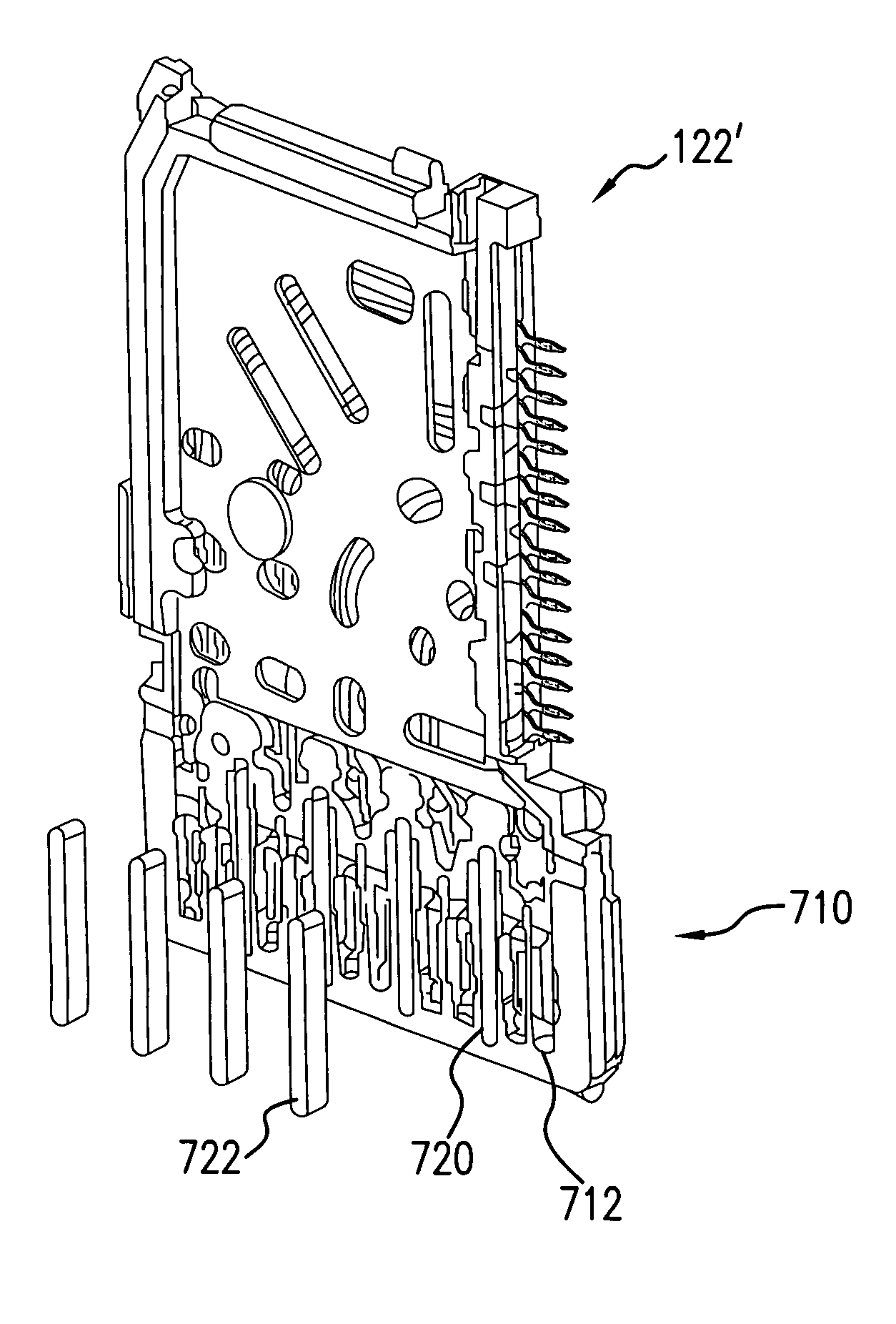
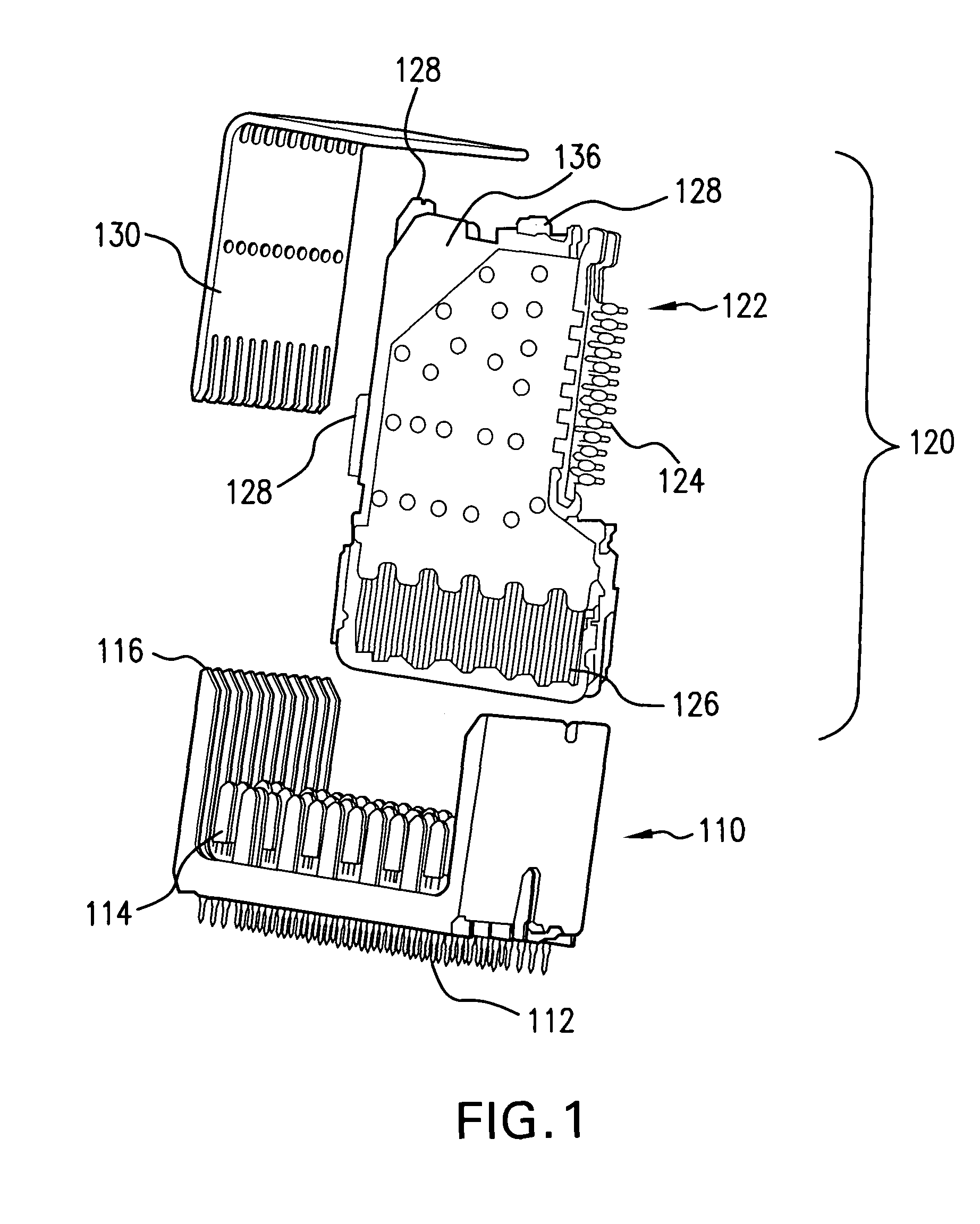
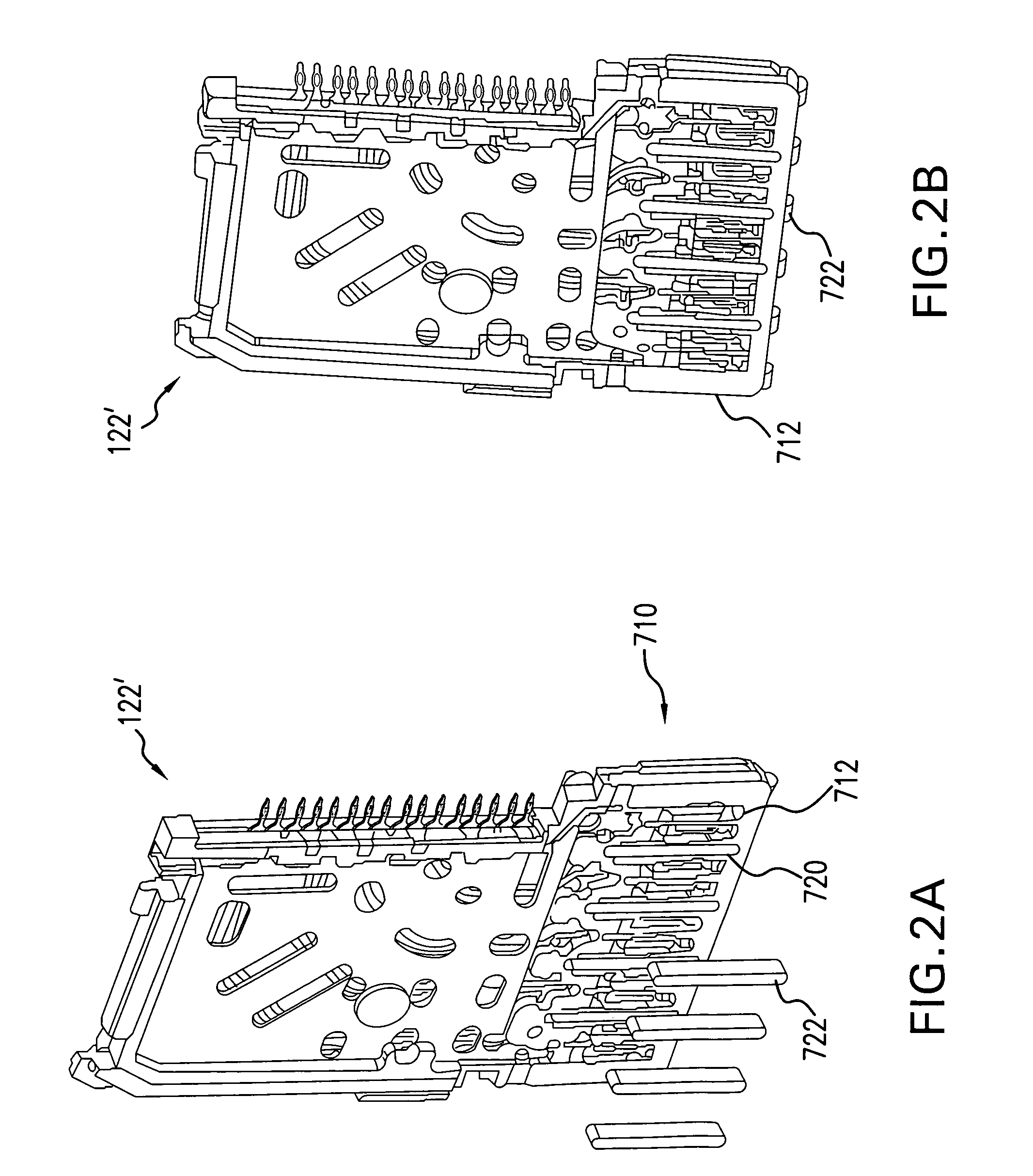
An electrical connector system includes a daughter card connector formed of a plurality of wafers. Each wafer is formed with cavities between the contacts of the signal conductors. The cavities are shaped to receive lossy inserts whereby crosstalk is reduced. The connector system may also or alternatively include a front housing formed with shield plates also to aid in reducing cross-talk. The front housing is adapted to mate between the wafers of the daughter card connector and a backplane connector of the electrical connector system. In an alternative embodiment, the front housing portion may include lossy conductive portions for cross-talk reduction.

Description

CROSS-REFERENCE TO RELATED APPLICATION[0001]This application claims priority to U.S. Provisional Patent Application Ser. No. 60 / 695,264, filed Jun. 30, 2005, the contents of which are incorporated herein by reference.BACKGROUND OF THE INVENTION[0002]1. Field of Invention[0003]This invention relates generally to electrical interconnection systems and more specifically to electrical interconnection systems, such as high speed electrical connectors, with improved signal integrity.[0004]2. Discussion of Related Art[0005]Electrical connectors are used in many electronic systems. Electrical connectors are often used to make connections between printed circuit boards (“PCBs”) that allow separate PCBs to be easily assembled or removed from an electronic system. Assembling an electronic system on several PCBs that are then connected to one another by electrical connectors is generally easier and more cost effective than manufacturing the entire system on a single PCB.[0006]Electronic systems...

Claims


Application Information

Patent Timeline
Patent Type & Authority Patents(United States)
IPC IPC(8): H01R13/502H01R13/6461H01R13/6474H01R13/658H01R13/6586H01R13/6599
CPCH01R13/514H01R12/52H01R13/518Y10T29/4922H01R13/6587
Inventor MANTER, DAVID PAULCOHEN, THOMAS S.
Owner AMPHENOL CORP
Learn More