
Magnetic resonance apparatus and method to acquire and display calibration images

a magnetic resonance and calibration image technology, applied in the field of calibration image acquisition and display, can solve the problems of small errors and inaccuracy in mr signal generation and acquisition, image artifacts, and slight differences, and achieve the effect of faster acquisition and high quality

Active Publication Date: 2011-12-27
SIEMENS HEALTHCARE GMBH +1
View PDF4 Cites 0 Cited by
  • Summary
  • Abstract
  • Description
  • Claims
  • Application Information

AI Technical Summary

Benefits of technology

[0010]An object of the present invention is to provide a method for acquisition and display of calibration images that optimizes the discovery (identification) of the ideal offset frequency so that a subsequent acquisition of measurement data leads to images with higher quality with simultaneously faster acquisition of the calibration images. Furthermore, it is an object of the invention to provide a magnetic resonance apparatus for implementation of such a method.
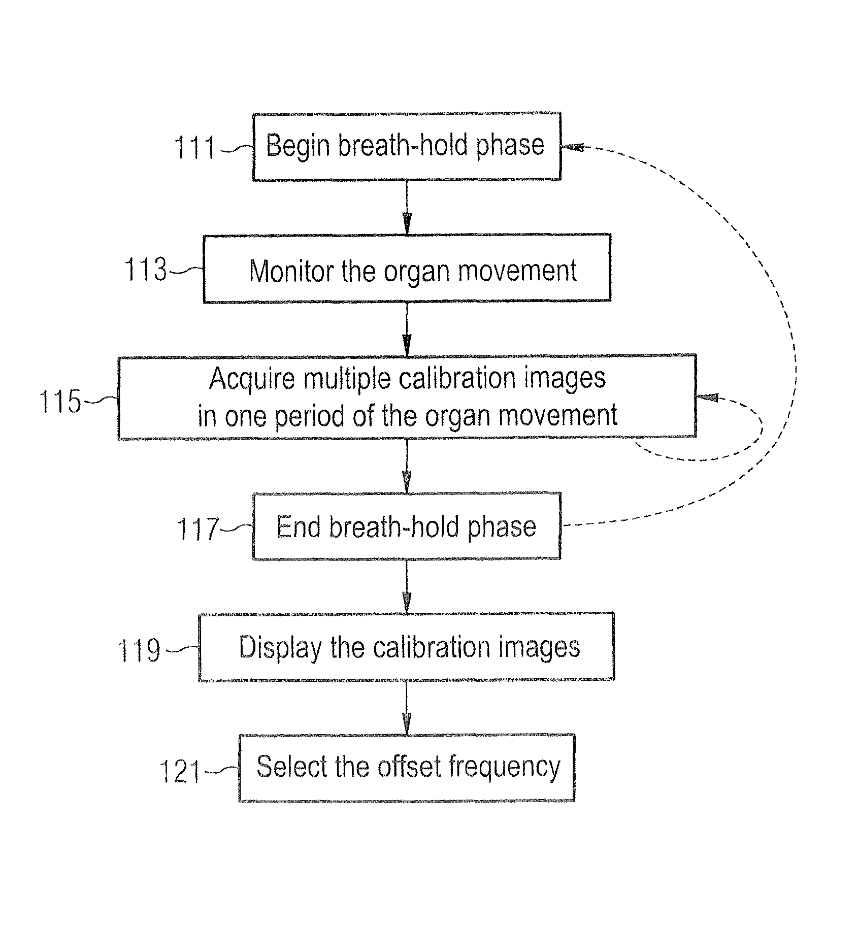
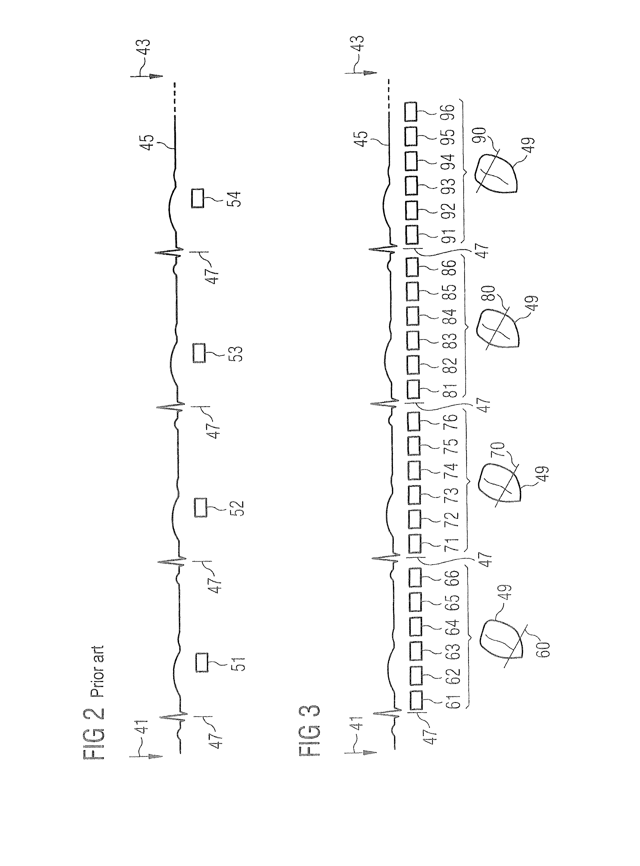
[0011]In the method according to the invention for acquisition and display of calibration images in a periodically moving organ with the aid of magnetic resonance technology, calibration images are acquired in a first step in that measurement data for multiple calibration images are acquired during a continuous period of the organ movement, wherein the multiple calibration images differ in their offset frequency and / or in their spatial position in the organ to be examined, and the calibration images are displayed to a user in a second step in a presentation manner that, from the visual quality of the respective images, allows the user to select (identify) the image acquired with the offset frequency that should then be used to acquire the diagnostic image.
[0012]In contrast to known methods with which measurement data for a calibration image are acquired only in a specific phase per cardiac cycle, the method according to the invention enables the acquisition of more calibration images in the same amount of time, which distinctly increases the flexibility in the design of the method. For example, more offset frequencies can be tested, and / or calibration images from many different slices can be acquired, without distinctly increasing the measurement time. The calibration images acquired in one period differ, for instance in their spatial position and / or in their offset frequency.
[0021]In another embodiment, those calibration images that differ in their spatial position relative to the subject to be examined are displayed in parallel (next to one another) in the display of the calibration images. In particular, a combination of these two embodiment variants results in an advantageous presentation. In this case, multiple slices are presented in parallel, and the movie presentation enables a sequential consideration of the different offset frequencies. It is thus simple for a user to identify the matching offset frequency.
[0023]The method is particularly advantageous when a TrueFISP sequence which is particularly susceptible to off-resonance effects is used as the sequence for measurement data acquisition.

Problems solved by technology

MR signal generation and acquisition are sensitive to small errors and inaccuracies in the technique that is used.
Effects known as the off-resonance effects are one cause of image artifacts.
For example, this slight difference can be the consequence of an insufficient shim or an insufficient frequency adjustment.
In the reconstructed image, this can often appear as band-shaped artifacts, which can considerably hinder an evaluation of measured data.

Method used


Image

  • Magnetic resonance apparatus and method to acquire and display calibration images
  • Magnetic resonance apparatus and method to acquire and display calibration images
  • Magnetic resonance apparatus and method to acquire and display calibration images

Examples


Embodiment Construction

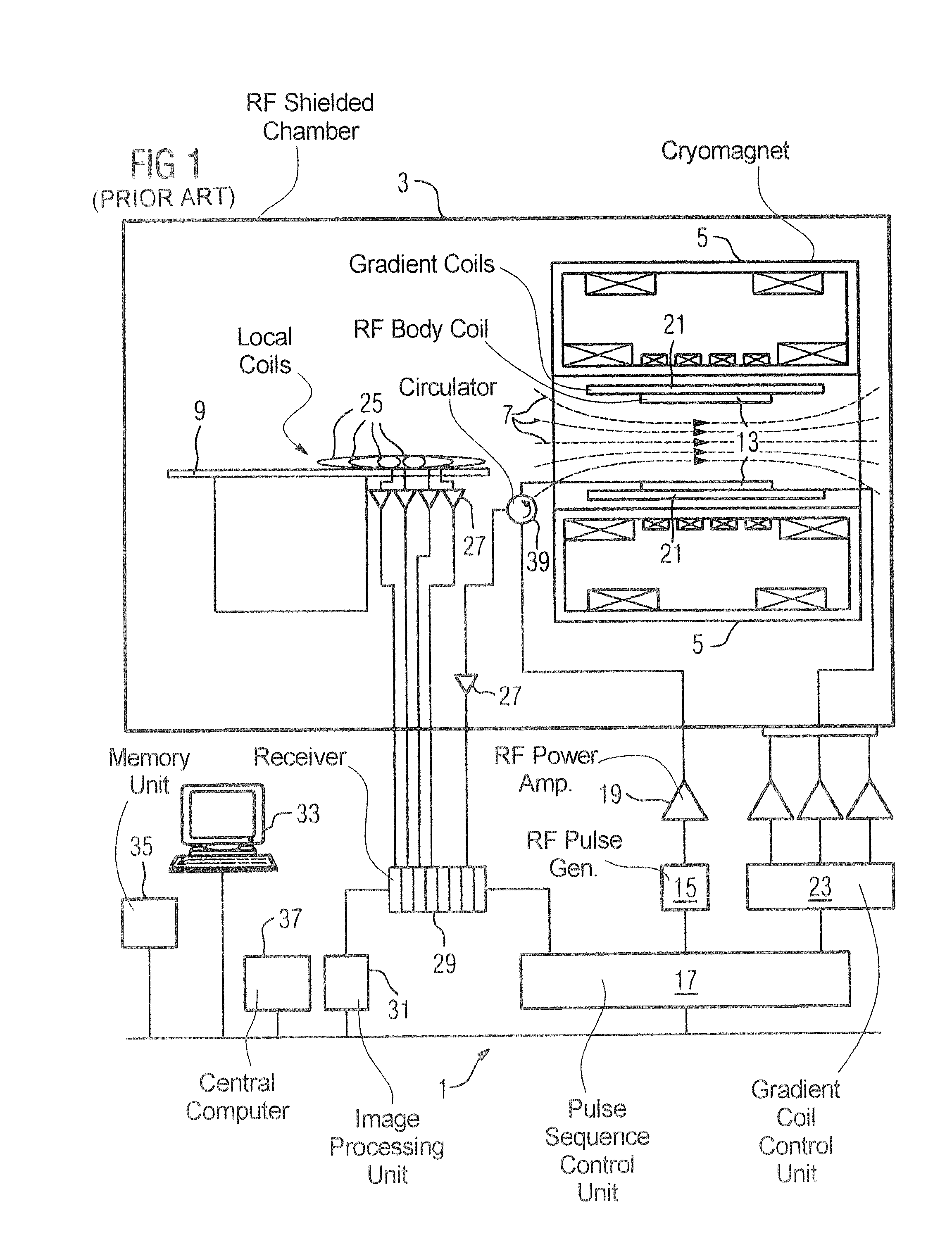
[0031]FIG. 1 schematically shows the design of a magnetic resonance apparatus 1 with its basic components. In order to examine a body by means of magnetic resonance imaging, different magnetic fields matches to one another as precisely as possible in terms of their temporal and spatial characteristics are radiated into the body.

[0032]A strong magnet (typically a cryomagnet 5 with a tunnel-shaped opening) arranged in a measurement chamber shielded against radio frequencies generates a strong, static basic magnetic field 7 that is typically 0.2 Tesla to 3 Tesla or more. A body or a body part (not shown here) to be examined is placed on a patient bed 9 and is positioned in a homogeneous region of the basic magnetic field 7.

[0033]The excitation of the nuclear spins of the body ensues via magnetic radio-frequency excitation pulses that are radiated via a radio-frequency antenna (shown here as a body coil 13). The radio-frequency excitation pulses are generated by a pulse generation unit ...


PUM


Abstract

In a method and magnetic resonance apparatus to acquire and present calibration images of a periodically moving organ with the use of magnetic resonance technology, calibration images are acquired by acquiring measurement data for multiple calibration images during one continuous period of the organ movement, the multiple calibration images differing in their offset frequency and / or in their spatial position in the organ to be examined, and the calibration images in a presentation manner that, from the visual quality of the respective images, allows the user to select (identify) the image acquired with the offset frequency that should then be used to acquire the diagnostic image are displayed to a user.

Description

BACKGROUND OF THE INVENTION[0001]1. Field of the Invention[0002]The present invention concerns a method to acquire and display calibration images in a periodically moving organ with the use of magnetic resonance technology. Furthermore, the invention concerns a magnetic resonance apparatus to implement such a method[0003]2. Description of the Prior Art[0004]Calibration images are used (among other things) in magnetic resonance imaging before diagnostically significant images of a subject to be examined are acquired and serve for the adjustment or, respectively, the optimization of the subsequent acquisition of the measurement data from which the diagnostically significant images are generated.[0005]Magnetic resonance technology (in the following the term “magnetic resonance” is also shortened to MR) is thereby a technique that has been known for several decades with which images of the inside of an examination subject can be generated. Described in a significantly simplified way, th...

Claims


Application Information

Patent Timeline
Patent Type & Authority Patents(United States)
IPC IPC(8): G01V3/00
CPCG01R33/543G01R33/58A61B2560/0223G01R33/5614G01R33/56325G01R33/5673
Inventor GREISER, ANDREASZUEHLSDORFF, SVEN
Owner SIEMENS HEALTHCARE GMBH
Learn More