Model driven diagnostics system and methods thereof

a diagnostic system and model technology, applied in the field of diagnostics, can solve the problems of consuming a lot of time and money to solve problems, requiring a lot of technical expertise of technicians, and the conventional methods used in conventional methods, so as to solve problems quickly and effectively

Active Publication Date: 2011-12-27
EDGEVERVE SYST
View PDF16 Cites 1 Cited by
  • Summary
  • Abstract
  • Description
  • Claims
  • Application Information

AI Technical Summary

Benefits of technology

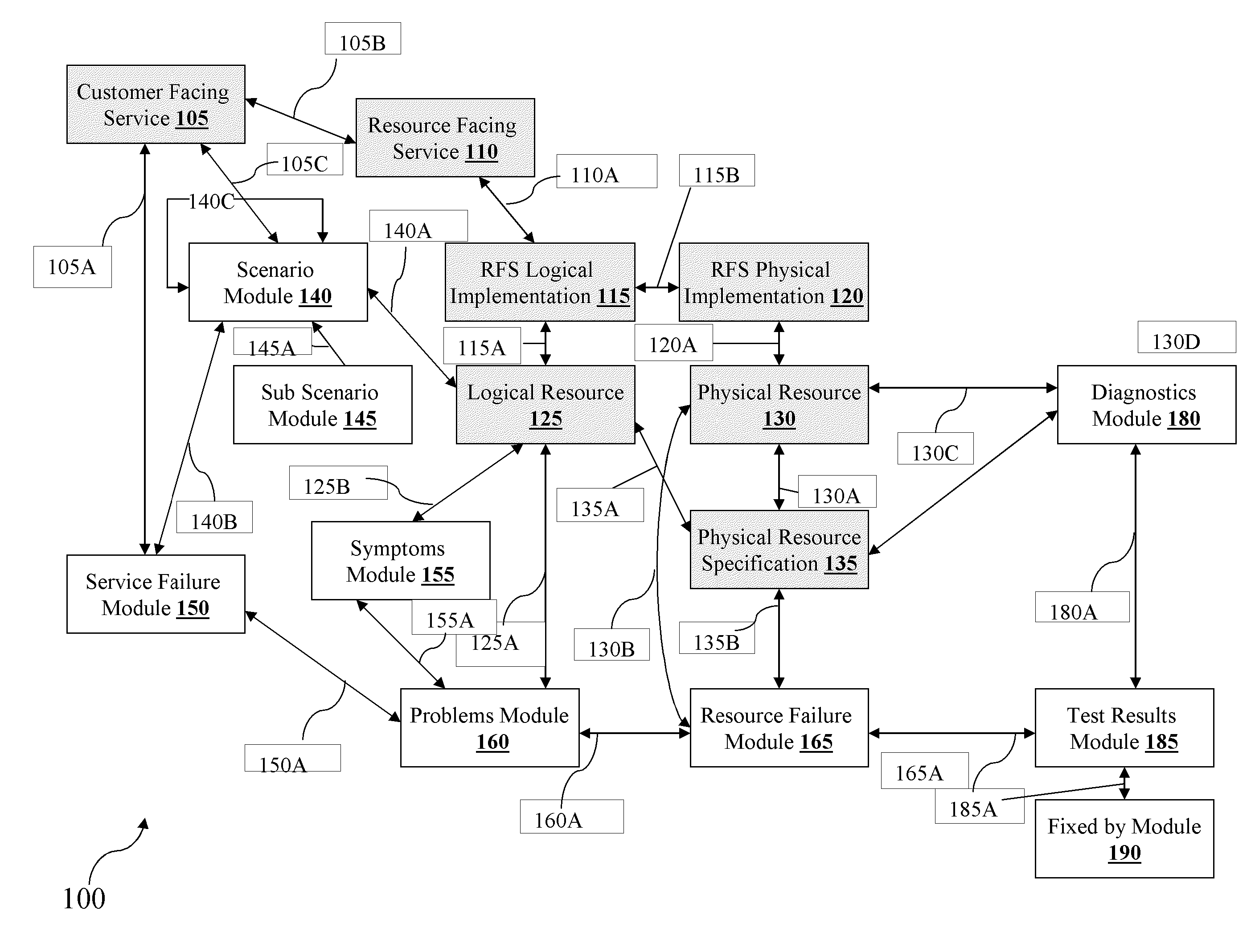
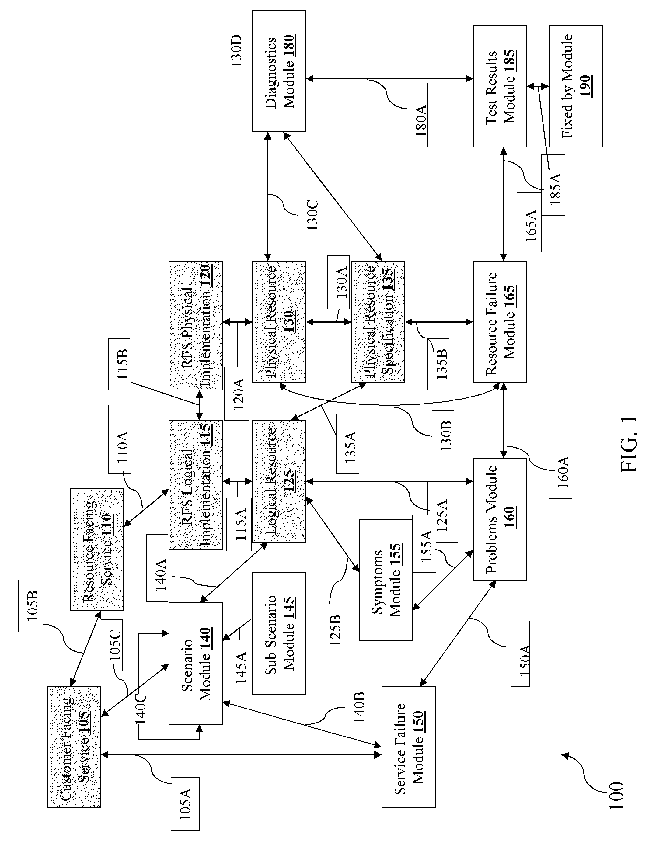
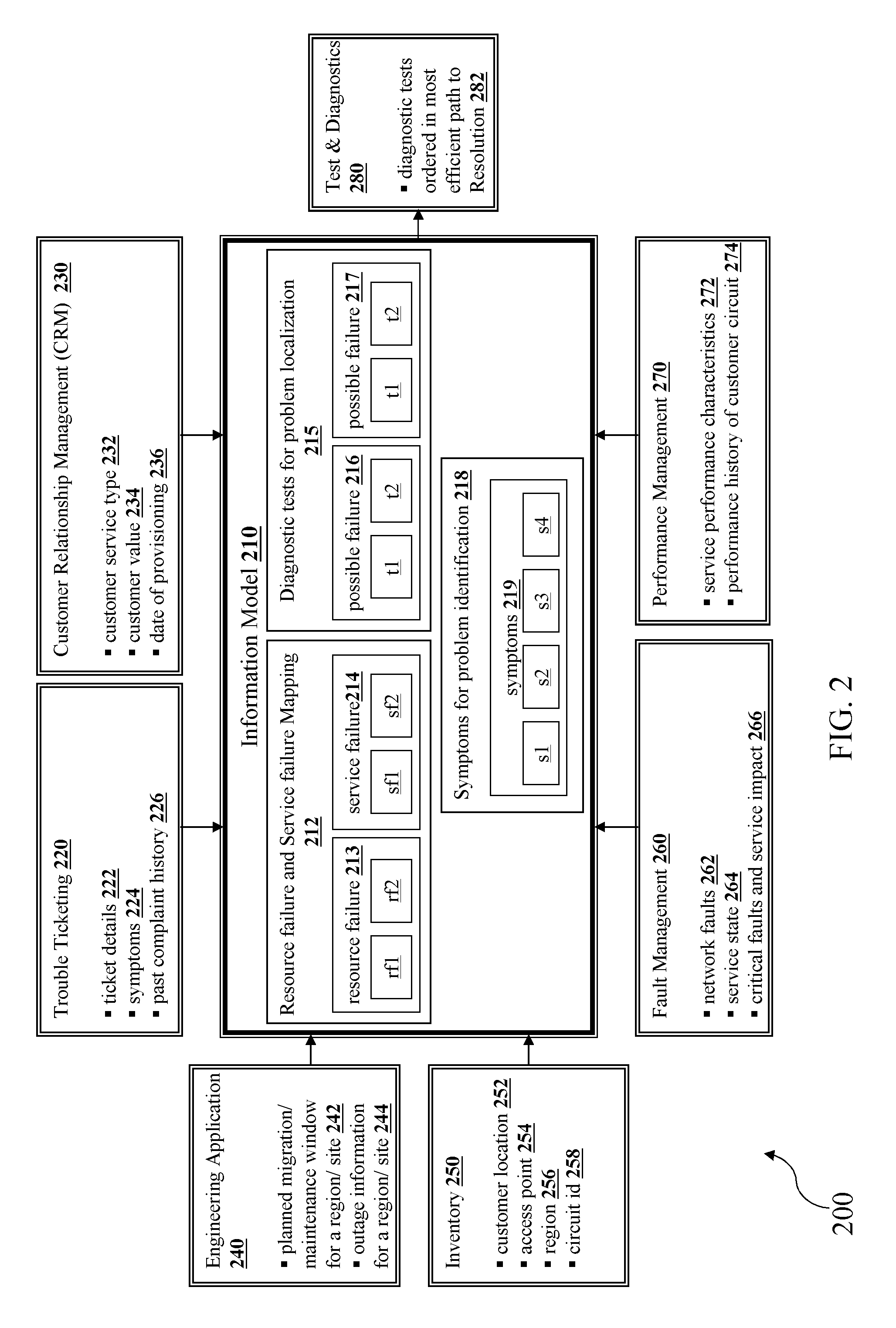
[0010]In yet another embodiment of the present technique, the approach may help a Communication Service Provider (herein also referred as “CSP”) to build the knowledge model before the service or product or both being rolled and make the Customer Support Representative (“herein also referred as “CSR”) to readily solve the problem in much faster and effective way. In another embodiment of the present technique, the knowledge model built by the experts may generate the diagnostic plan dynamically for resolving the problem by considering the symptoms or a costs or a planned engineering maintenance work or a network migration details or an early service failure about a new service rolled in the market or a network alarms or a performance thresholds or a trouble history results or combinations thereof.

Problems solved by technology

However, the method used to resolve trouble faced either by the customer or in the network requires particular expertise of the agents and may even take a lot of time to isolate.
If the problem is not apparent from the outset, the technicians may narrow down the problem space by a process of elimination by running the various diagnosis tests, which may again consume lot of time and money to resolve the problem.
Also, the techniques used in the conventional methods require lot of expertise of the technicians and hence involves people dependencies in resolving the problem.
Often, the techniques used by the agents or technicians either in the customer support or in the network support for resolving the problem are disparate.

Method used


Image

  • Model driven diagnostics system and methods thereof
  • Model driven diagnostics system and methods thereof
  • Model driven diagnostics system and methods thereof

Examples


Embodiment Construction

[0019]The following description is full and informative description of the best method and system presently contemplated for carrying out the present invention, which is known to the inventors at the time of filing the patent application. Of course, many modifications and adaptations will be apparent to those skilled in the relevant arts in view of the following description in view of the accompanying drawings and the appended claims. While the system and method described herein are provided with a certain degree of specificity, the present technique may be implemented with either greater or lesser specificity, depending on the needs of the user. Further, some of the features of the present technique may be used to advantage without the corresponding use of other features described in the following paragraphs. As such, the present description should be considered as merely illustrative of the principles of the present technique and not in limitation thereof, since the present techni...


PUM


Abstract

A method to perform a diagnostic test in an integrated support platform having a plurality of services is disclosed. The method includes a process of building at least one or more knowledge model for each of the plurality of services in the integrated support platform. The process of building the knowledge model includes determining one or more failure(s) of each component and at least one associated symptom to identify the one or more failures and constructing a framework for the diagnostic test associated to the one or more failures. The framework comprising the diagnostic test may be created by at least one of an execution plan based on the most efficient path for determining the failure. The method further includes performing the diagnostic test for resolving one or more failures of each component by using the framework based on the built knowledge model for the plurality of services.

Description

TECHNICAL FIELD[0001]The present invention relates to a diagnostics, and more particularly, to a method of resolving failures in a telecommunication domain by at least one of the customer support operation or network support operation or both through the diagnostics constructed dynamically using a model driven approach in an integrated support platform having a plurality of services.BACKGROUND[0002]A method of providing a customer support or a network support is well known in a telecommunication domain. The method typically includes utilizing a knowledge management for diagnosing trouble or problem in the customer support and a network management system for diagnosing problem in the network support. The usage of the knowledge model for diagnosing the customer problem may be done either by a customer support representative (CSR) or by an agent or technicians. Similarly, the usage of the network management system for diagnosing the network problem may be done either by the agent or th...

Claims


Application Information

Patent Timeline
Patent Type & Authority Patents(United States)
IPC IPC(8): G06F11/00
CPCH04L41/0631H04L41/0663H04L41/16
Inventor PRAMIDI, SAILAJA SVIVIANO, TOMNATARAJAN, SWAMINATHAN
Owner EDGEVERVE SYST
Why Eureka
Try Eureka