Magnetoelastic torque sensor with ambient field rejection

a magnetic torque sensor and ambient field technology, applied in the field of magnetic field sensors, can solve the problems of sensor teaching, patent may be susceptible to other magnetic fields of exterior origin, and the configuration of the invention disclosed in the '059 patent is error-prone, so as to improve the uniformity of rotation signals

Active Publication Date: 2012-01-03
METHODE ELETRONICS INC
View PDF29 Cites 89 Cited by
  • Summary
  • Abstract
  • Description
  • Claims
  • Application Information

AI Technical Summary

Benefits of technology

[0018]In this scheme, we utilize the fact that, beyond a certain distance between the near field source and the sensors, a magnetic field from an external near field source(s) decreases in a substantially linear fashion in relation to the distance from the external near field source. Magnetic field sensors placed closest to the external near field sources detect the largest near field value, magnetic field sensors placed farthest from external near field source detect the smallest near field value, and magnetic field sensors in the center sense an average value of the nearest and farthest sets of magnetic field sensors. The magnetic field sensors at the central region have opposite sensing polarity to the magnetic field sensors at the right side and left side regions. Thus, the near field measured by the primary magnetic field sensors at the central region is the same magnitude and opposite sign from the averaged values of the near field measured by the secondary magnetic field sensors at the right and left regions. The interconnects to the field sensors in combination with the associated electronics are configured so as to average the values of the left and right side regions and sum that average with the value of the center region sensor which, because it is oriented with an opposite polarity, effectively cancels the effects of the near field measurement error.
[0023]It is another object of the present invention to provide a torque sensor and method for using the same in which is provided an arrangement of magnetic field sensors proximate to the torque sensor such that the signal from the sensors measuring the torque-dependent magnetic flux from the active region may be compensated to substantially eliminate the effects of a near magnetic field source on the torque sensor.
[0024]Briefly described, those and other objects and advantages of the present invention are accomplished, as embodied and fully described herein, by a method for reducing the noise in a signal from a torque sensor caused by near magnetic field sources, the method including the steps of providing a torque sensor, receiving a first primary signal upon the application of a torque; receiving a second and a third secondary signals; and adjusting the first signal using the second and third signals thereby compensating for the effects of the near magnetic field source. The torque sensor includes at least a longitudinally extending member; a magnetoelastically active region directly or indirectly attached to / or forming a part of the surface of the member, the active region having at least one region magnetized in a first substantially circumferential direction in such a manner that torque applied to the member is proportionally transmitted to the active region; a plurality of primary magnetic field sensors arranged proximate the at least one region for outputting a first signal corresponding to a torque-dependent magnetic flux emanating from the active region; at least one secondary magnetic field sensor axially spaced in a first direction by a predetermined first distance from the plurality of active magnetic field sensors for outputting a second signal corresponding to an ambient magnetic flux emanating from the near magnetic field source; at least one secondary magnetic field sensor axially spaced in a second direction opposite the first direction by the pre-determined first distance from the plurality of active magnetic field sensors for outputting a third signal corresponding to the ambient magnetic flux emanating from the near magnetic field source.

Problems solved by technology

Because magnetic fields, in the context of their measurement, are fungible, the sensor taught in the '555 patent may be susceptible to other magnetic fields of exterior origin.
In practice, the configuration of the invention disclosed in the '059 patent is error-prone in the presence of locally divergent magnetic fields because the two magnetic field sensors experience different magnitudes of the divergent magnetic fields.
The difference in magnetic fields between the two magnetic field sensors originating from a near field source combines non-uniformly with torque induced magnetic fields and leads to a false torque value.
There are numerous other types of near field sources that can compromise an accurate torque-dependent field measurement.
Another would be the nearby presence of a ferromagnetic structure that distorts the shape and direction of the earth's magnetic field, creating a localized area in which the magnetic flux is concentrated in an undesirable direction.
While the shielding method noted above can be effective for external magnetic fields perpendicular to the axial direction of a shield in the form of a tube, this shield is very vulnerable to external magnetic fields in the axial direction of the tube which is open at both ends.
Flux director structures typically operate by gathering the radial flux component of the torque dependent magnetic field, and are therefore well suited for rejecting axially directed flux of external origin, however, flux directors tend to be susceptible to external fields perpendicular to the axis of the shaft.
However, such a combination has other shortcomings that limit its desirability in many applications including cost and packaging within the design
Frequently, demagnetization is not perfect, and there remains a remanent magnetic field in the column or shaft after the MPI process.
This relatively large external magnetic field can be directly transferred to the field sensors inside the shield, and can be non-uniformly summed with the torque-induced magnetic fields, corrupting the torque measurement.
This means that there is no totally effective way to protect or shield external magnetic fields propagating through the shaft with current techniques.
An additional disadvantage of the shielding method is that any deformation of the shield device caused by mechanical impact or extreme temperature change can affect the relative position of the field sensors and the shield, which can lead to unbalancing of far field values between two sensor fields operating in pairs that are oppositely oriented.
This would result in compassing failure.
Furthermore, in most torque sensor applications, packaging space is limited, and in many cases there is no room for a shield or flux director.
In addition, the added financial cost for those components is not insignificant because materials with high permeability tend to have high percentages of nickel, the pricing of which is quite volatile.

Method used


Image

  • Magnetoelastic torque sensor with ambient field rejection
  • Magnetoelastic torque sensor with ambient field rejection
  • Magnetoelastic torque sensor with ambient field rejection

Examples


Embodiment Construction

[0047]Several preferred embodiments of the invention are described for illustrative purposes, it being understood that the invention may be embodied in other forms not specifically shown in the drawings. The figures will be described with respect to the system structure and methods for using the system to achieve one or more of the objects of the invention and / or receive the benefits derived from the advantages of the invention as set forth above.

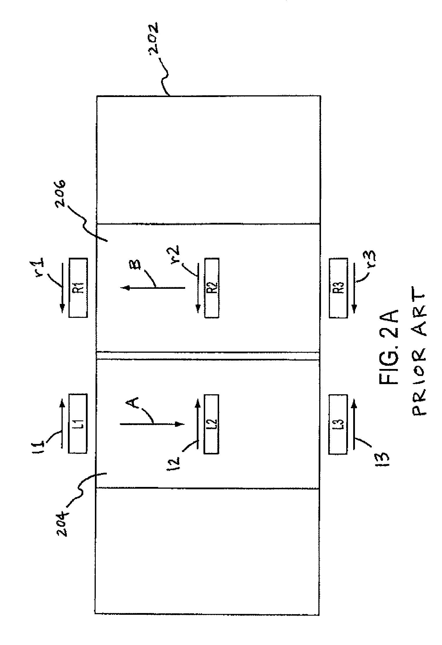
[0048]U.S. Pat. No. 5,520,059 describes a torque sensor having a transducer and magnetic field vector sensor. The torque sensor is mounted on a shaft which is part of a machine, and it rotates about a central longitudinal axis. A torque having a magnitude T is applied at one portion of the shaft and is transmitted thereby to another portion of the shaft where the motion of the shaft due to the torque T performs some useful work. The torque may be in a clockwise or counterclockwise direction when looking at the visible end of the shaft, but ...


PUM

PropertyMeasurementUnit
distanceaaaaaaaaaa
torqueaaaaaaaaaa
magnetic fluxaaaaaaaaaa

Abstract

The present invention involves a method and apparatus for canceling the effects of magnetic field noise in a torque sensor by placing three sets of magnetic field sensors around a shaft, the first set of field sensors being placed in the central region of the shaft and the second and third sets of field sensors being placed on the right side and left side of the field sensors placed at the central region, respectively. A torque-induced magnetic field is not cancelled with this arrangement of field sensors but a magnetic near field from a near field source is cancelled.

Description

CROSS-REFERENCE TO RELATED APPLICATIONS[0001]The present application claims priority under 35 U.S.C. §119(e) to U.S. Provisional Patent Application No. 61 / 036,619, entitled “MAGNETOELASTIC TORQUE SENSOR WITH AMBIENT FIELD REJECTION”, filed on Mar. 14, 2008, the entire disclosure of which is incorporated herein by reference.BACKGROUND OF THE INVENTION[0002]1. Field of the Invention[0003]The invention is related in general to systems and methods involving the use of magnetic field sensors, and in particular the invention is related to systems, methods, and apparatus involving sensors and circuits that cancel magnetic field noise while measuring torque-induced magnetic fields.[0004]2. Description of the Related Art[0005]U.S. Pat. No. 5,351,555, the disclosure of which is incorporated herein by reference in its entirety, discloses a single circularly magnetized region in which the magnetic dipoles tilt in the presence of torsional stress, thereby emanating an externally measurable magne...

Claims


Application Information

Patent Timeline
Patent Type & Authority Patents(United States)
IPC IPC(8): G01L3/14G01L3/00G01B7/14
CPCG01L3/102G01R33/07
Inventor LEE, SEONG-JAE
Owner METHODE ELETRONICS INC
Why Eureka
Try Eureka