Methods and systems for leakage cancellation in radar equipped munitions

Inactive Publication Date: 2007-04-19
HONEYWELL INT INC
View PDF43 Cites 24 Cited by
  • Summary
  • Abstract
  • Description
  • Claims
  • Application Information

AI Technical Summary

Benefits of technology

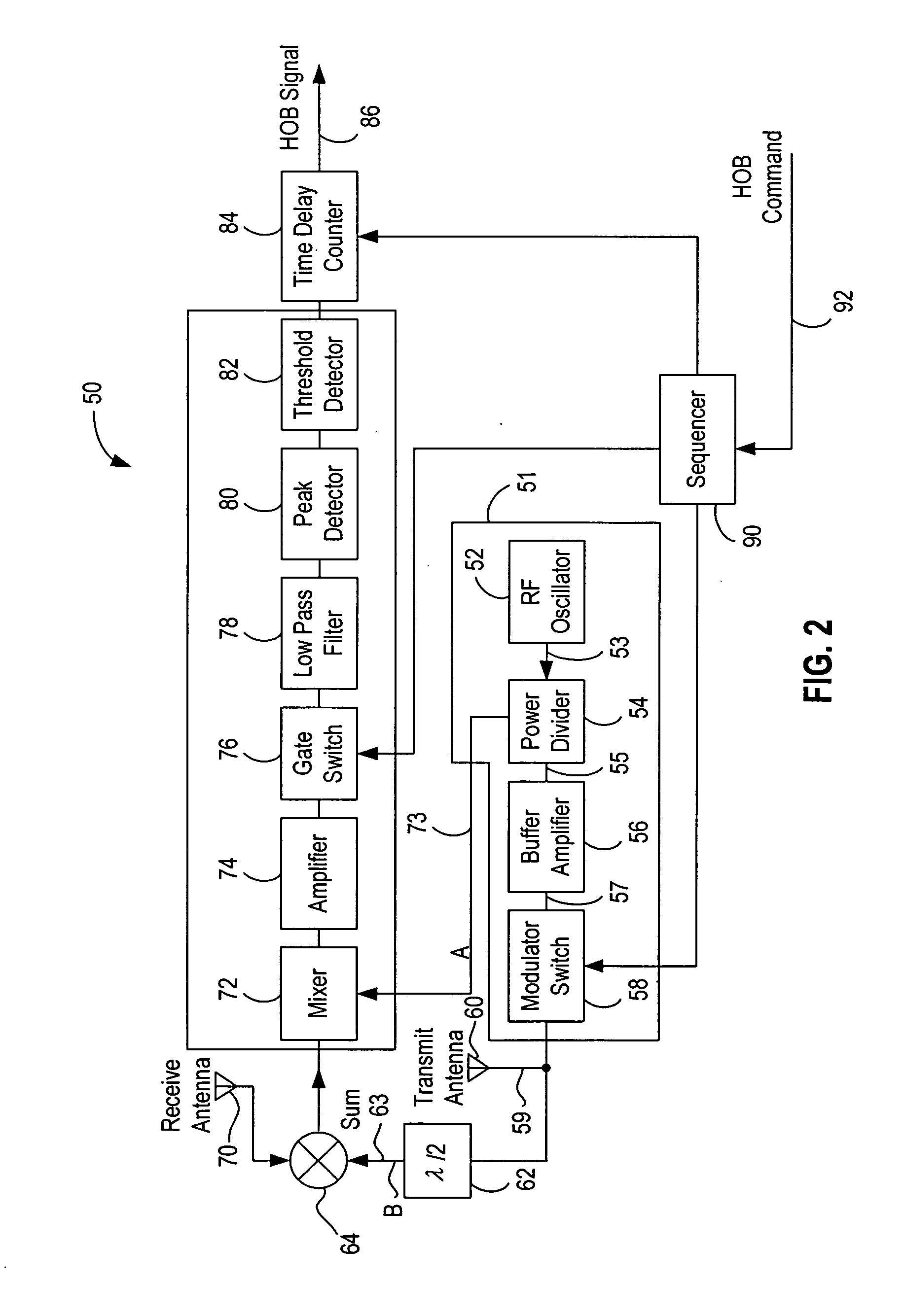
[0005] In one aspect, a radar sensor configured to control detonation of a munition is provided. The radar sensor comprises a radar transmitter comprising a radar transmit antenna, a radar receiver comprising a radar receive antenna, and a leakage cancellation unit. The leakage cancellation unit is configured to cancel effects of an antenna leakage signal transmitted by the radar transmit antenna and received by the radar receive antenna. The leakage cancellation unit provides a signal to the radar receiver that is substantially out of phase with the leakage signal received by the radar receiver.
[0006] In another aspect, a method which allows tracking of altitude to ground level with a radar sensor is provided. The method comprises providing a signal to be transmitted by the radar sensor as a transmitted

Problems solved by technology

However, dropping conventional munitions from a low altitude exposes the aircraft and crew to air defenses, for example, anti-aircraft artillery and surface-to-air missiles since.
Alternatively, to deliver munitions in high numbers, it is frequently necessary to fly an undesirably large number of missions which is expensive, time consuming, and exposes more aircraft

Method used


Image

  • Methods and systems for leakage cancellation in radar equipped munitions
  • Methods and systems for leakage cancellation in radar equipped munitions
  • Methods and systems for leakage cancellation in radar equipped munitions

Examples


Example

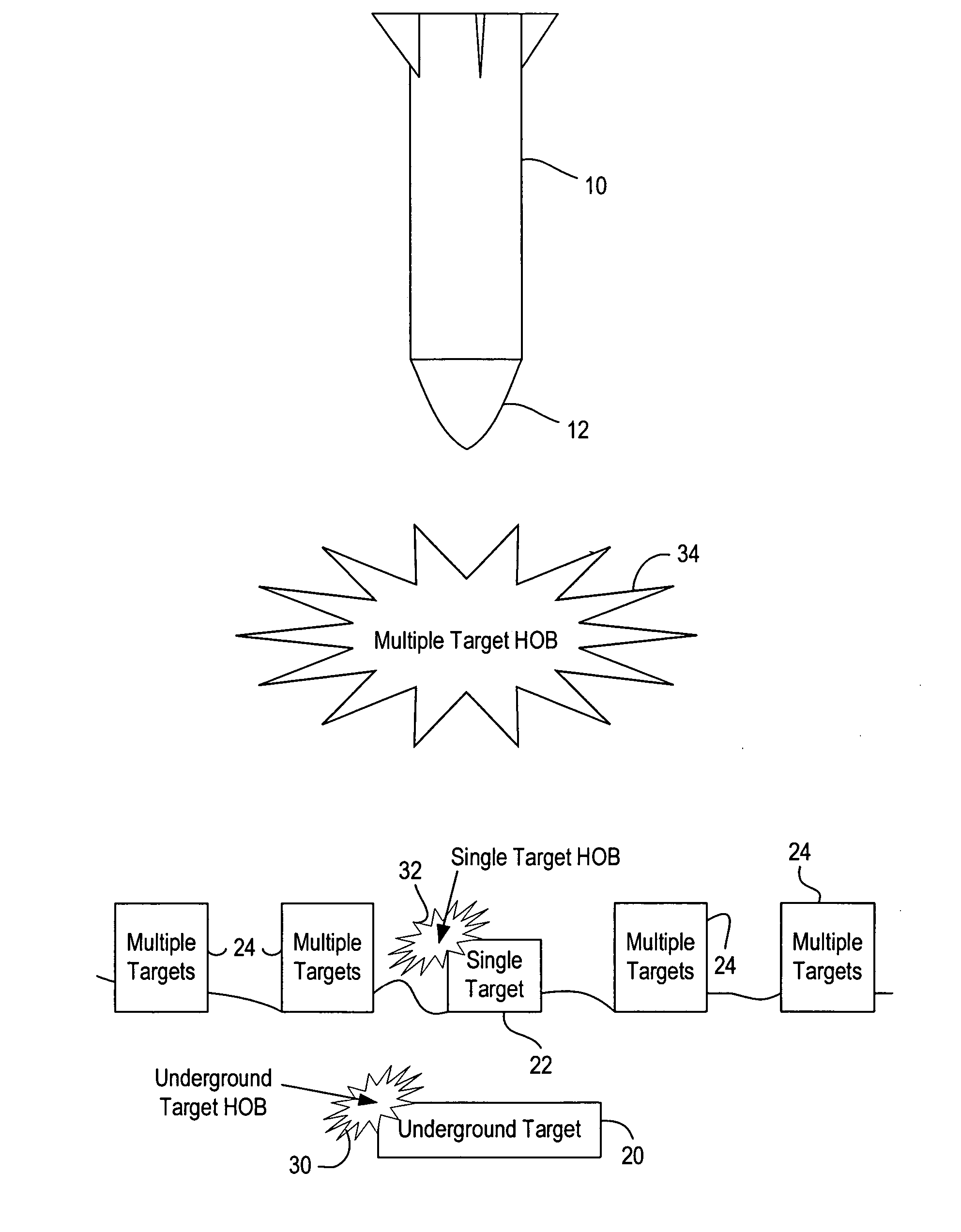
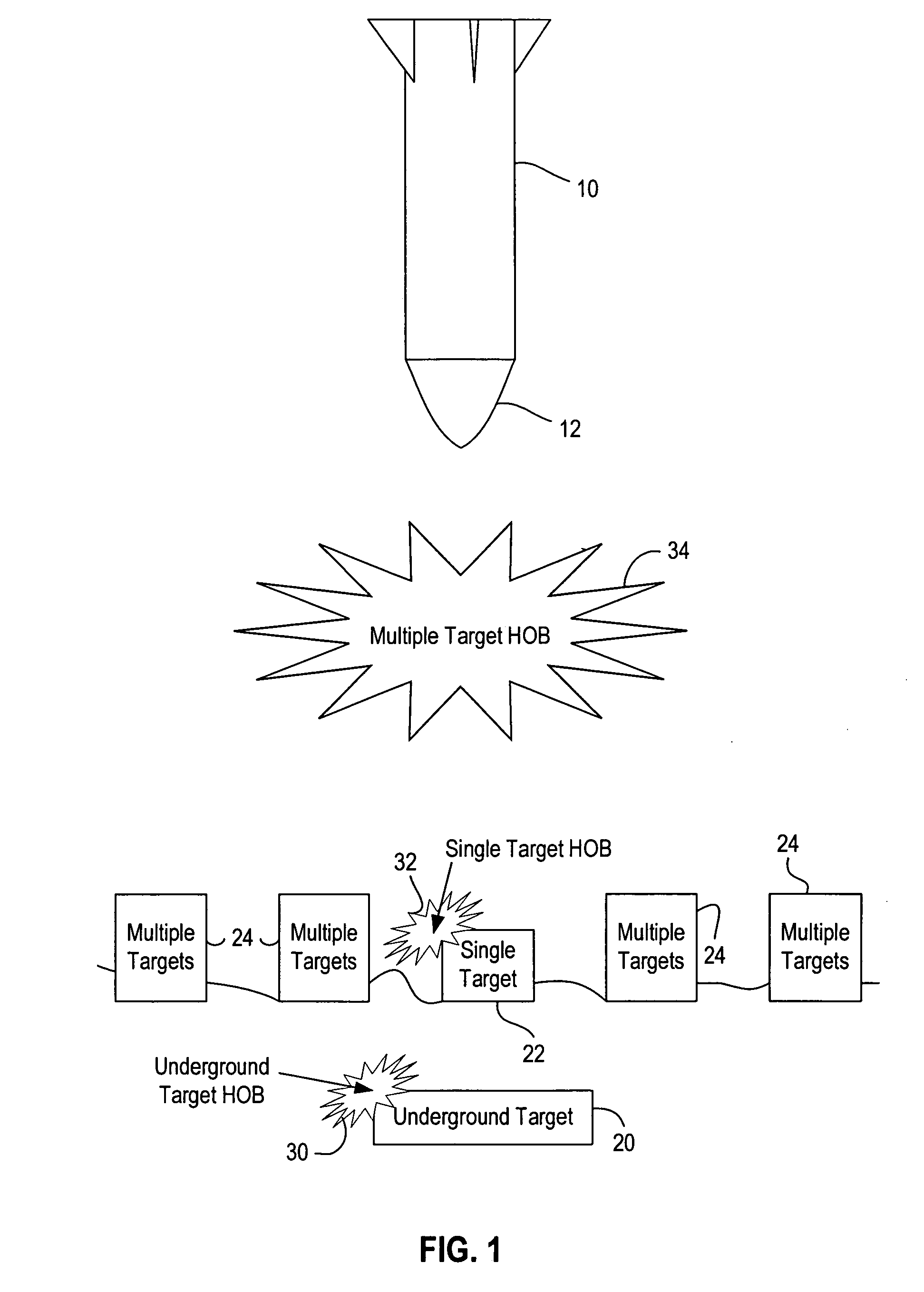
[0013] A small, low cost, detonation altitude (e.g., height of burst) radar sensor incorporating a programmable height of burst capability for multi-functional bombs, submunitions, and low cost missile applications is described. The detonation altitude is programmable in that there are different detonation scenarios including above ground detonation, ground level detonation, and even below ground detonation. The radar sensor is incorporated into the munition and includes radar transmit and radar receive antennas that are close in proximity to one another. However, close spacing between the transmit and receive antennas results in an operational problem in known radar systems since a leakage signal between the two antennas typically causes interference with a ground return signal. Such a leakage signal generally interferes with the capability to operate properly at low altitude operation causing either inaccuracies or tracking of the leakage signal rather than the ground return signa...


PUM


Abstract

A radar sensor configured to control detonation of a munition is described that includes a radar transmitter comprising a radar transmit antenna, a radar receiver comprising a radar receive antenna, and a leakage cancellation unit. The leakage cancellation unit is configured to cancel effects of an antenna leakage signal transmitted by the radar transmit antenna and received by the radar receive antenna. To cancel the effects of the leakage signal, the leakage cancellation unit is configured to provide a signal to the radar receiver that is substantially out of phase with the leakage signal received by the radar receiver.

Description

BACKGROUND OF THE INVENTION [0001] This invention relates generally to controlling detonation of weapons, and more specifically, to methods and systems for controlling a height, or altitude, of munition detonation. [0002] Conventional munitions dropped or launched from aircraft is either released with a high accuracy, or in large numbers, in order to effectively destroy a desired target. To achieve a high accuracy, it is frequently necessary to drop such munitions from an undesirably low altitude. However, dropping conventional munitions from a low altitude exposes the aircraft and crew to air defenses, for example, anti-aircraft artillery and surface-to-air missiles since. Alternatively, to deliver munitions in high numbers, it is frequently necessary to fly an undesirably large number of missions which is expensive, time consuming, and exposes more aircraft and crew to air defenses. [0003] To overcome these problems, smart munitions have been developed. Some smart munitions utiliz...

Claims


Application Information

Patent Timeline
IPC IPC(8): G01S13/08
CPCG01S7/038G01S13/882
Inventor BACKES, GLEN B.THOMAS, STEVEN H.
Owner HONEYWELL INT INC
Why Eureka
Try Eureka