
Nmos ldo psrr improvement using power supply noise cancellation

a power supply and noise cancellation technology, applied in the field of low dropout voltage regulators, can solve problems such as introducing switching noise, limited use, and increasing system complexity

Active Publication Date: 2014-11-20
TEXAS INSTR INC
View PDF5 Cites 26 Cited by
  • Summary
  • Abstract
  • Description
  • Claims
  • Application Information

AI Technical Summary

Benefits of technology

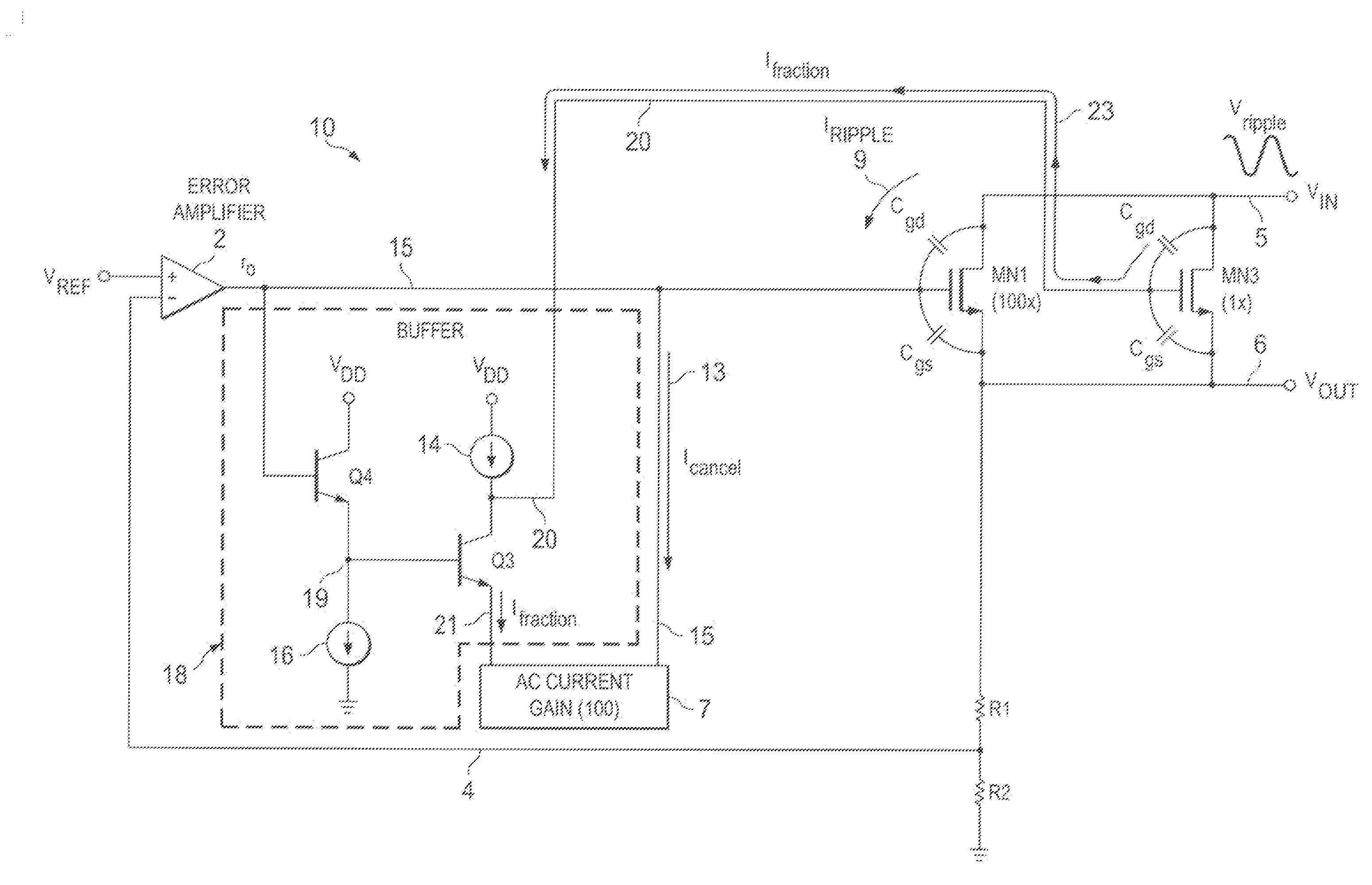
The invention provides a low dropout voltage regulator that can cancel out the effect of ripple voltage present on the supply voltage input. This is achieved by using an error amplifier, a N-channel pass transistor, a N-channel cancellation transistor, and a biasing circuit. The N-channel cancellation transistor produces an AC injection cancellation current that is a predetermined proportion of the ripple current, which cancels out the ripple current in the first conductor. The AC current gain circuit then doubles the cancellation current to generate a ripple cancellation current that cancels out the ripple current in the first conductor and prevents it from affecting the output voltage. Overall, this invention allows for more stable and accurate voltage regulation.

Problems solved by technology

The penalties of using an external biasing voltage rail include limited use of N-channel pass transistor LDO's to systems where an extra high voltage rail is available and increased system complexity.
The penalties for using an on-chip charge pump needed for N-channel LDO pass transistors include introducing switching noise and increasing the cost for integrated circuit die area.
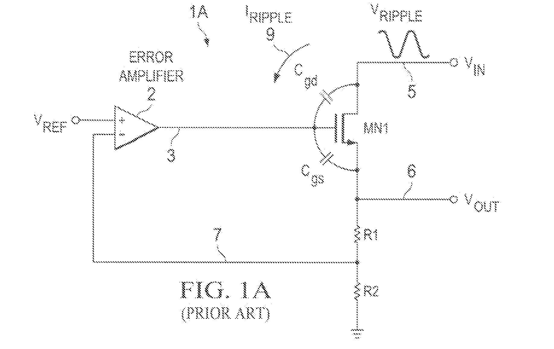
It has been very challenging to obtain high PSRR in voltage regulators having low dropout voltages because there is a trade-off between achieving high PSRR and reducing the size of the pass transistor.
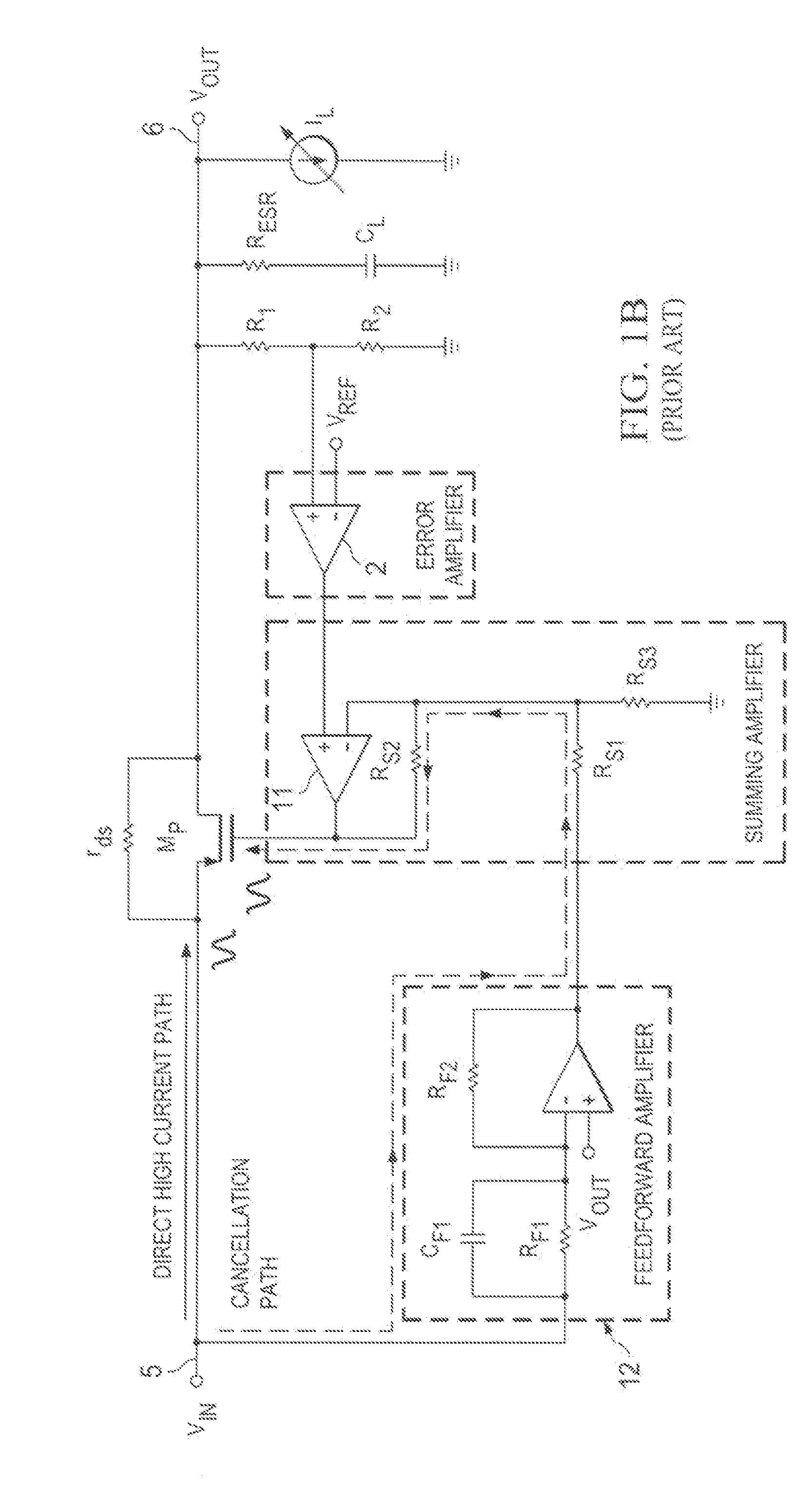
The cancellation is not so effective because most of the noise coupled from VIN to VOUT passes through the output conductance gds of pass transistor MP.
Also, it should be noted that although the cancellation technique of prior art FIG. 1B is effective for a P-channel pass transistor LDO, it is not applicable for an N-channel pass transistor LDO.
Furthermore, the disclosed technique is not applicable to an N-channel pass transistor.

Method used


Image

  • Nmos ldo psrr improvement using power supply noise cancellation
  • Nmos ldo psrr improvement using power supply noise cancellation
  • Nmos ldo psrr improvement using power supply noise cancellation

Examples


Embodiment Construction

[0033]Referring to FIG. 2, a low-dropout (LDO) voltage regulator 10 includes an error amplifier 2 and a large N-channel pass transistor MN1 having its drain connected by input conductor 5 to the unregulated noisy power supply input voltage VIN. The source of pass transistor MN1 is connected to the output conductor 6 on which the regulated output voltage VOUT is generated. (Note that the source and drain connections of N-channel pass transistor MN1 in FIG. 2 are opposite to the source and drain connections of the P-channel pass transistors shown in Prior Art FIGS. 1B and 1C.) The (+) input of error amplifier 2 is coupled to a reference voltage VREF, which typically is generated by a conventional band gap reference circuit. A resistive voltage divider circuit including feedback resistors R1 and R2 feeds the scaled-down regulated output voltage VOUT on conductor 6 back via conductor 4 to the (−) input of error amplifier 2. The output of error amplifier 2 is coupled by conductor 15 to d...


PUM


Abstract

Power-supply ripple rejection (PSRR) at high frequencies is improved for an LDO voltage regulator with an NMOS pass transistor (MN1). A ripple voltage (Vripple) present on the input voltage causes a ripple current (Iripple) through parasitic gate-drain capacitance of the pass transistor. A small ripple current (Ifraction) proportional to the ripple current (Iripple) is generated and amplified to generate a cancellation current (Icancel). The cancellation current is drawn from the gate of NMOS pass transistor (MN1) to cancel the ripple current so that no net ripple current flows through the finite output impedance of an error amplifier (2), to thereby achieve the PSRR improvement.

Description

BACKGROUND OF THE INVENTION[0001]The present invention relates generally to LDO (low dropout) voltage regulators, and more particularly to improvements in LDO voltage regulators which utilize an N-channel pass transistor and also provide both high PSRR (power supply rejection ratio, also referred to as power supply ripple rejection) and low VIN-to-VOUT voltage “headroom” at high frequencies. A conventional LDO, with either an NMOS or a PMOS pass device, is essentially a 3-terminal device having VIN, VOUT, and GND terminals. VIN not only delivers power to VOUT, but also is used as a supply voltage, sometimes referred to as a “supply rail”, for the LDO control circuit. In the case of N-channel pass transistor LDO, VIN can no longer be used as the supply rail for controlling the gate of an N-channel pass transistor of an LDO as VIN-to-VOUT becomes lower and lower (to be less than 0.7 volts), because N-channel MOS transistors need at least one gate-to-source (VGS) voltage, typically aro...

Claims


Application Information

Patent Timeline
Patent Type & Authority Applications(United States)
IPC IPC(8): H02M3/158
CPCH02M3/158G05F1/575H02M1/15H02M1/0022
Inventor WANG, JIANBAO
Owner TEXAS INSTR INC
Learn More