Hose and tubing assemblies and mounting systems and methods

a technology of hoses and tubing, which is applied in the direction of machine supports, transportation and packaging, etc., can solve the problems of high cost or inferior bracket to the hose or the bracket to the tubing joinder, and the inability to rotate and axially move the tubing when overmolding to smooth metal tubing, so as to prevent abrasion of the hose

Active Publication Date: 2012-01-03
THE GATES CORP
View PDF18 Cites 7 Cited by
  • Summary
  • Abstract
  • Description
  • Claims
  • Application Information

AI Technical Summary

Benefits of technology

[0009]The present invention solves various performance problems associated with previous hose or tubing mounting designs. For example, damage or fracture of thermoplastic materials resulting from installation bolt fastener forces may be addressed by embodiments of the present invention, wherein at least a portion of a rigid metal mounting bracket is not encapsulated by the overmold, particularly the portion of the mounting bracket that includes bolt holes or the like. As a result mounting bolts are allowed to bear on the exposed metal rather than on unreinforced resin or the like as is often the case in previous brackets. As a further example, the lack of adequate mechanical or adhesive integrity of the hose component to an associated bracket is addressed in embodiments of the present invention by entirely overmolding the bracket and hose junction with a resin, or the like that can bond, mechanically, thermally and / or chemically with both the bracket and the hose or tube. Embodiments of the present invention also alleviate any need for elastomeric bushings or the like to be installed between hose components and metal brackets, as the present invention eliminates any relative movement between the bracket and the hose or tube. Additionally, an embodiment of the present invention can be employed in a hose assembly through a single step, relatively low skill-level procedure. Hence, adoption of the present invention in hose assemblies can result in reduced complexity of components and a simplification of manufacturing processes leading to reduced manufacturing and installation costs.
[0010]The combination of the insert over mold and hose or tube through the present invention by insert molding, such as through the use of pressure injection molding of the plastic overmold material, provides a robust assembly able to meet strenuous application and system requirements. This system robustness may be especially important in heavy duty applications, such as large trucks and heavy equipment. For example, a metal insert described provides robustness to resistance of clamping torques and pressures at the mounting surfaces. Additionally, a metal insert provides robustness to axial and rotational forces applied to the assembly resulting from system requirements. Advantageously, embodiments that employ a metal insert that partially encompasses the hose or tube can retain a hose or tube in place, at least to some degree, in the event that the over molded plastic material is damaged. Further, insert injection molding of the components is an economically efficient method of providing the function of the components in an assembly. As a further measure, the metal insert can contain cutaway portions and or reduced dimensions of thickness or area of the component resulting in weight savings. Preferably the overmolded plastic material provides an adjusted fit to both the hose and the metal insert components through controlled pressure molding of the material and by shrinkage of the material resulting from the molding process and shrinkage of the material after molding. Thereby, the overmolded material can provide radial forces capable of maintaining axial and rotational position on the hose preventing abrasive damage to the hose component. As a further feature, the over molded material can contain engraving or branding.
[0011]The over molded material can be disposed in such a manner to provide a mounting surface of the assembly to the system, including the aforesaid axial and radial positioning, as well as contact with system components such as frame members, while positioning the hose component away from direct contact with such system components. Additionally, the hose used in the assembly may contain a textile or metal outer surface, a polymeric elastomeric outer surface, or combinations of these outer surfaces which can contribute to the robustness of the assembly to axial and rotational stresses.
[0013]Yet other embodiments of the present invention may include an assembly of one or more hoses or tubes, and an over molded plastic material which provides conformity of the hose to bends for routing the hose, with or without the use of a bracket insert associated with and / or encompassing a portion of some or all of the hoses and tubes. These embodiments provide connective bundling of two or more hoses or tubes in an assembly and may thereby provide environmental abrasion resistance and other advantages. Further, the use of a cured overmold that fuses, or at least mechanically bonds, to a surface of a hose through contraction of the overmold when it sets up to a relatively resilient rigidity can provide vacuum collapse resistance for a hose thus overmolded, and may provide thermal protection for the hose.
[0015]Further, in accordance with any of the above embodiments, a thermoplastic material molded around a hose can be chosen to provide for protection of the hose against abrasive damage to the hose from other components in the hose application environment and also chosen to provide thermal insulation protection of the hose to the environment. Foamed Polyphenylene Sulfide (PPS) sleeve might be a rigid, thermally protective sleeve material that could be used. Other embodiments might include ringed structures of overmolded thermoplastic material that adhere to the hose outside diameter and which prevent vacuum collapse of the hose. Additionally such overmolded rings may serve the function to space a hose away from a structure and prevent abrasion of the hose against the structure.

Problems solved by technology

However, existing bracket designs have performance problems, including: damage or fracture of thermoplastic materials resulting from forces applied to bolts or similar fasteners during installation; lack of adequate mechanical or adhesive integrity of the hose component to the coated or uncoated metal or plastic clips resulting in relative motion between the hose and the system components during service; displacement of elastomeric bushings installed between hose components and metal brackets; and similar problems.
Additional problems can stem from complexity of components and manufacturing processes which may lead to high costs or inferior bracket to hose or bracket to tubing joinder resulting from efforts to cut cost or reduce manufacturing times.
It is also known that overmolding to smooth metal tubing has issues with rotational and axial movement of the tubing with respect to the overmolded components due to the low coefficient of friction between the molding material and the tube.
However, the insert may not encompass the hose and may only be deployed adjacent to the hose.

Method used


Image

  • Hose and tubing assemblies and mounting systems and methods
  • Hose and tubing assemblies and mounting systems and methods
  • Hose and tubing assemblies and mounting systems and methods

Examples


Embodiment Construction

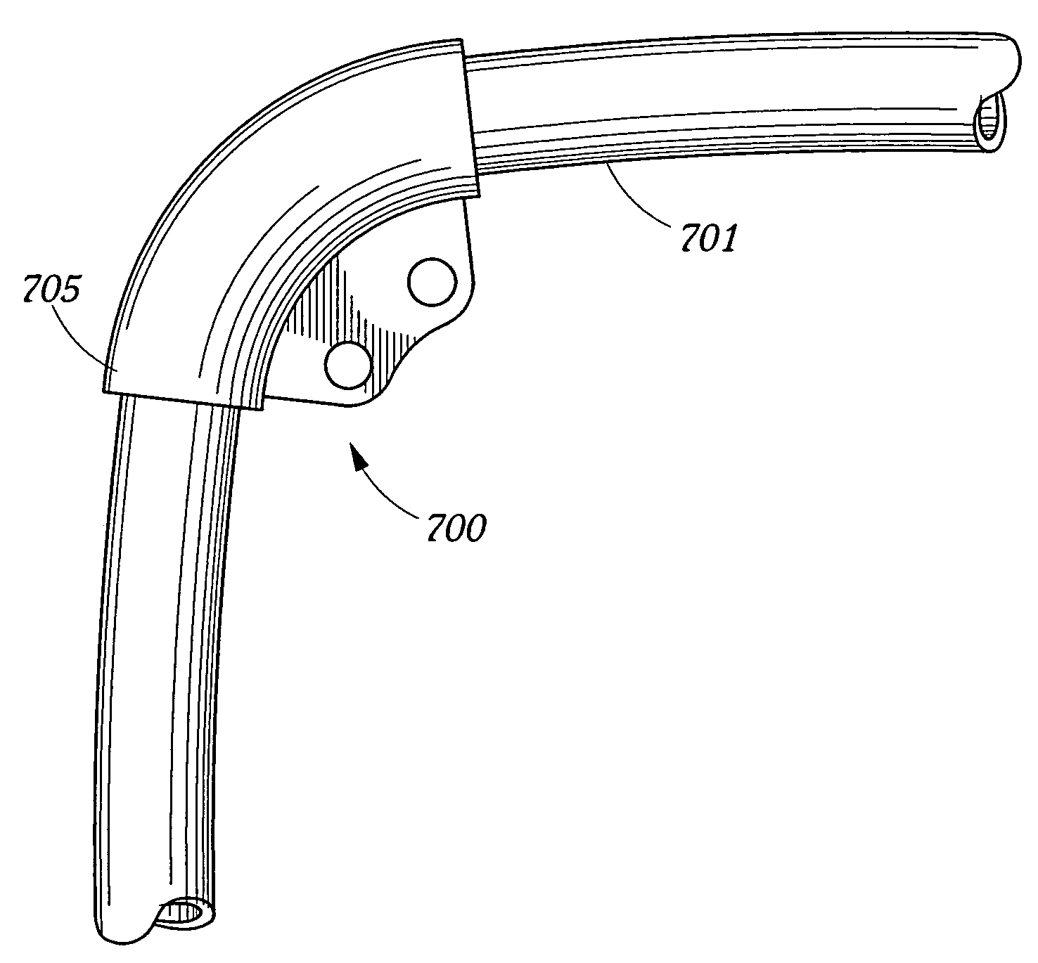
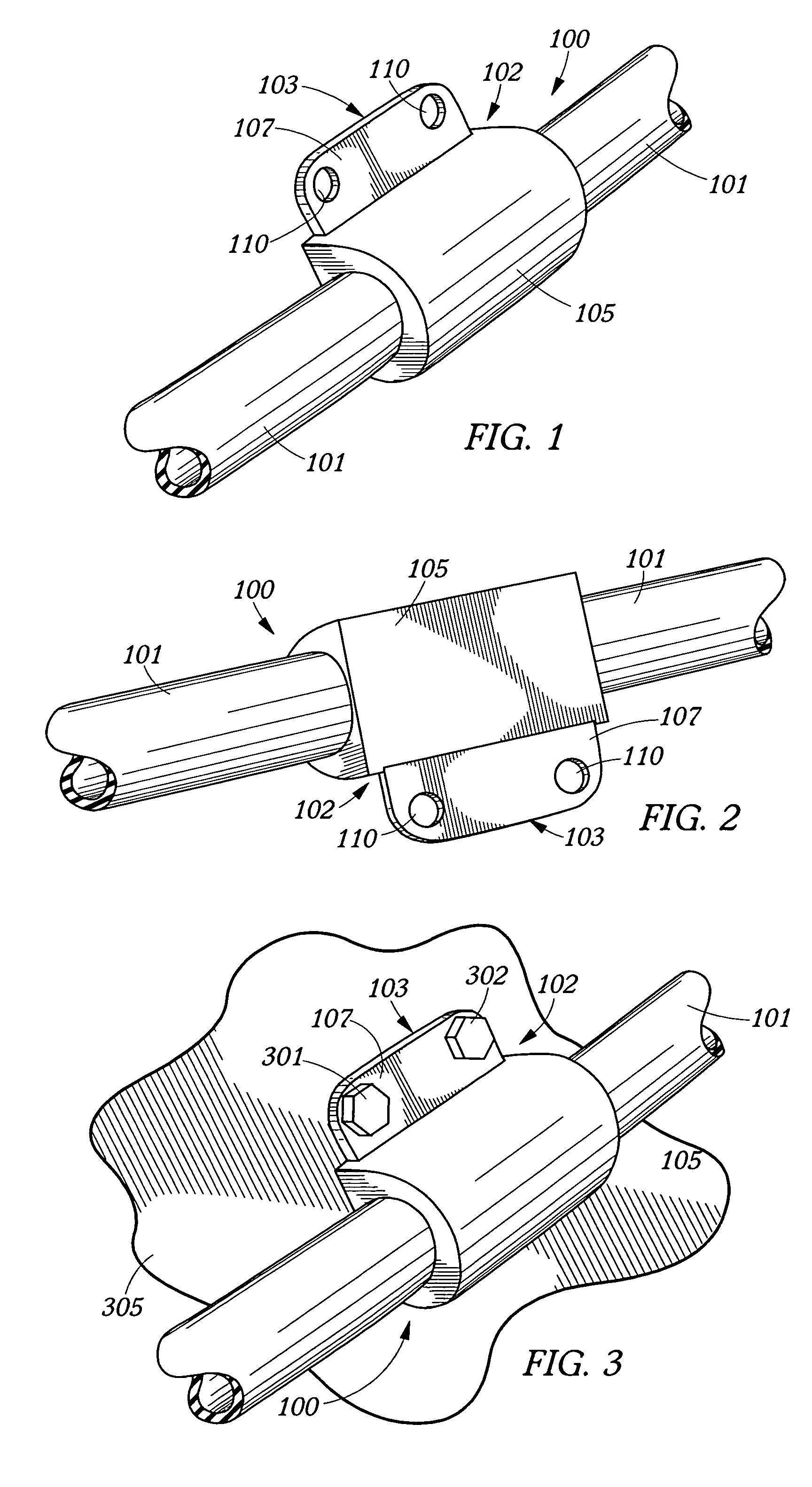
[0029]In accordance with embodiments of the present invention, a hose assembly, such as hose assembly 100 illustrated in FIGS. 1 and 2 might be deployed as a system to secure length of hose 101 in placed on a structure, such as shown in FIG. 3. The hose may be flexible and have a resilient rubber exterior, or the like. However, the exterior of the hose may have textile braid exterior, or the like. Additionally, the present invention may also incorporate tubing, either rigid or flexible, in place of hose 101. Rigid tubing may be metal tubing, or the like, and flexible tubing may be plastic.

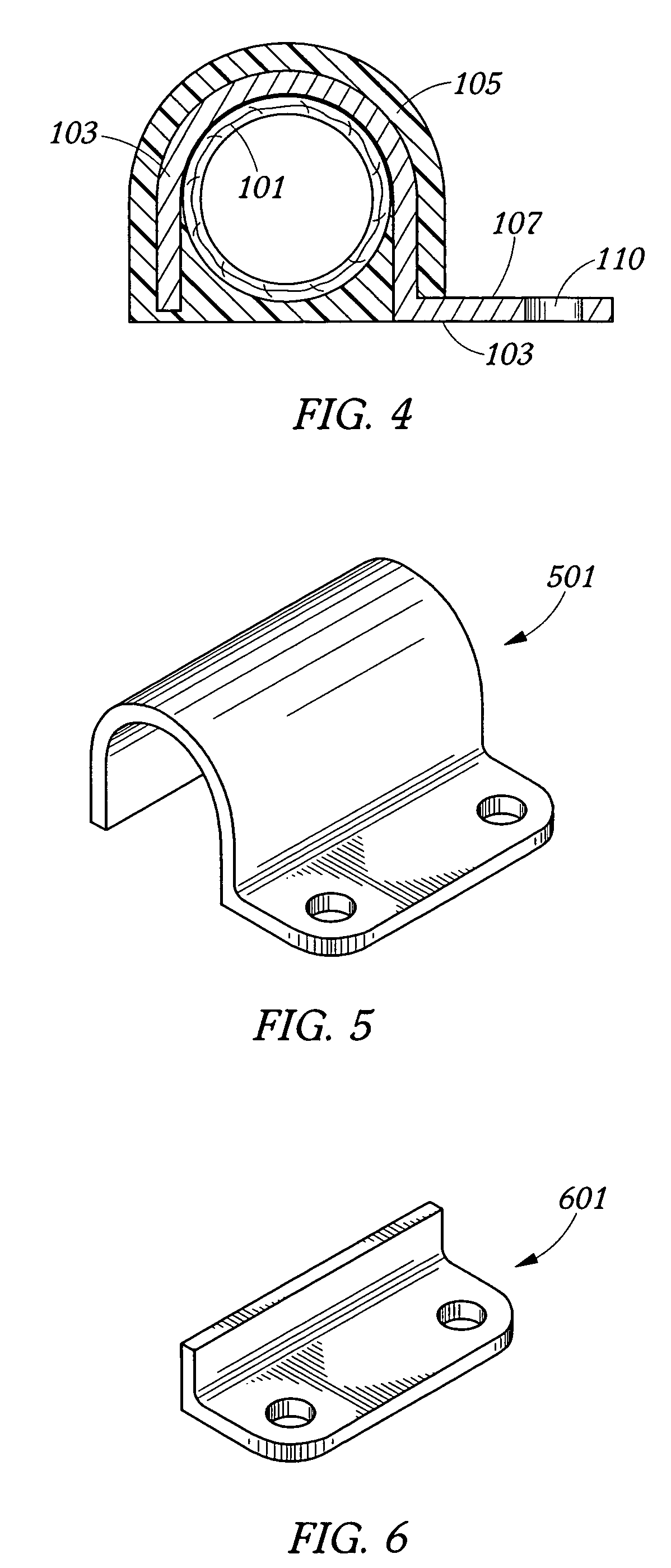
[0030]Hose assembly 100 also comprises bracket 102. The bracket includes rigid insert 103 and resilient overmold 105, encapsulating at least a portion of the insert and at least a portion of the hose associated with the insert. Preferably, as shown in cross sectional FIG. 4, this overmold is at least partially fused or otherwise mechanically bonded or joined with an exterior of the hose or tube. Th...


PUM


Abstract

A hose assembly includes a length of hose and a bracket. The bracket includes a rigid insert and a resilient overmold encapsulating at least a portion of the insert and mechanically bonding with at least a portion of an exterior of the hose. A method to produce this assembly may employ thermoplastic injection molding and include the steps of associating the rigid insert with the length of hose and overmolding the rigid insert and a section of the length of hose associated with the rigid insert with the resilient material, thereby encapsulating a portion of the insert and mechanically bonding the resilient material with the section of the length of the hose. A portion of the rigid insert may extend from the bracket and provide amounting holes and a bearing surface for mounting fasteners.

Description

BACKGROUND OF THE INVENTION[0001]1. Field of the Invention[0002]This invention relates generally to flexible hoses and bracketry for mounting such hoses and rigid tubing. More particularly, the present invention relates to hose or tubing assemblies including a hose or tube, a metal insert, and an overmolded thermoplastic mounting bracket.[0003]2. Description of the Prior Art[0004]Typically one of several different methods or designs for securing hose and / or tube assemblies to equipment will be employed. Such hose assemblies typically consist of a hose, length of rigid, and end fitting fluid connectors. Typically such designs are required to provide an ability to position and maintain the hose assembly relative to other components and protect the hose component of the assembly from mechanical damage, including damage incurred while mounting the hose assembly. Current designs may include: bolted metal brackets and elastomeric bushings; elastomeric coated or uncoated metal or plastic c...

Claims


Application Information

Patent Timeline
Patent Type & Authority Patents(United States)
IPC IPC(8): B65H75/34
CPCF16L3/1233F16L11/122Y10T137/6918
Inventor RAILSBACK, LAYNE
Owner THE GATES CORP
Why Eureka
Try Eureka