Method for providing homologation markings

a technology of homologation and markings, applied in the field of providing markings, can solve the problems of complex change of laser markings, inability to implement, and inability to achieve the effect of simple and quick technology

Active Publication Date: 2021-03-11
ROBERT BOSCH GMBH
View PDF0 Cites 0 Cited by
  • Summary
  • Abstract
  • Description
  • Claims
  • Application Information

AI Technical Summary

Benefits of technology

[0006]An object of the present invention is to create a method for providing markings, which may be updated in a technically simple and quick manner.

Problems solved by technology

Such a change of the laser marking, however, is complex with an increasing number of homologation markings and cannot be implemented on a daily basis.

Method used


Image

  • Method for providing homologation markings
  • Method for providing homologation markings
  • Method for providing homologation markings

Examples


Embodiment Construction

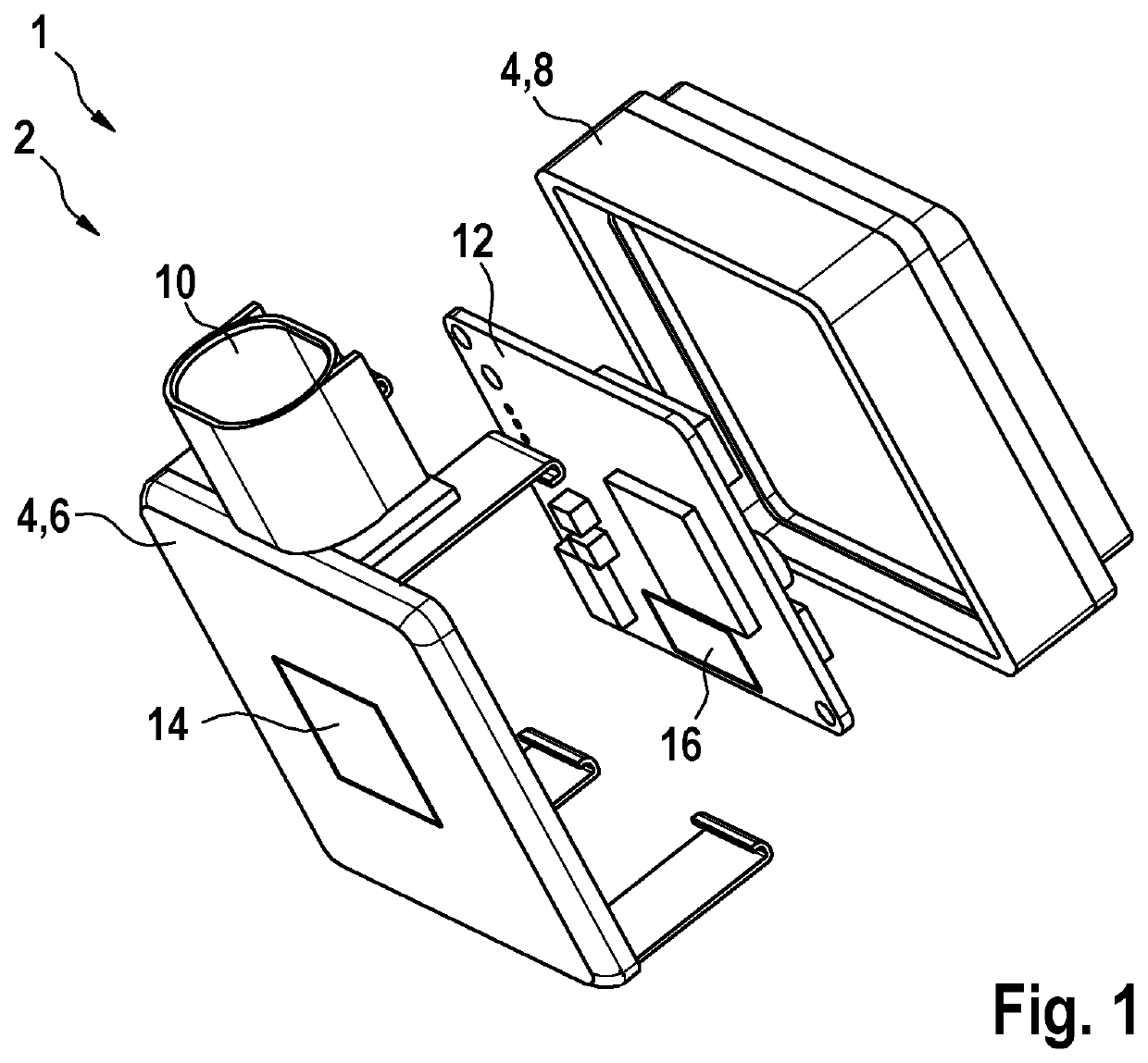
[0032]FIG. 1 shows a schematic exploded view of a component system 1 according to one specific embodiment according to the present invention. Component system 1 includes a component 2, which is configured as a radar sensor by way of example.

[0033]Component 2 includes a housing 4, which is divided into two housing halves 6, 8. Housing 4 includes a terminal 10 for the energy-conducting and data-conducting connection of component 2.

[0034]Terminal 10 is connected to a circuit board 12 or a functional unit of component 2. Circuit board 12 may, for example, include a receiving antenna and a transmitting antenna including corresponding electronic activation.

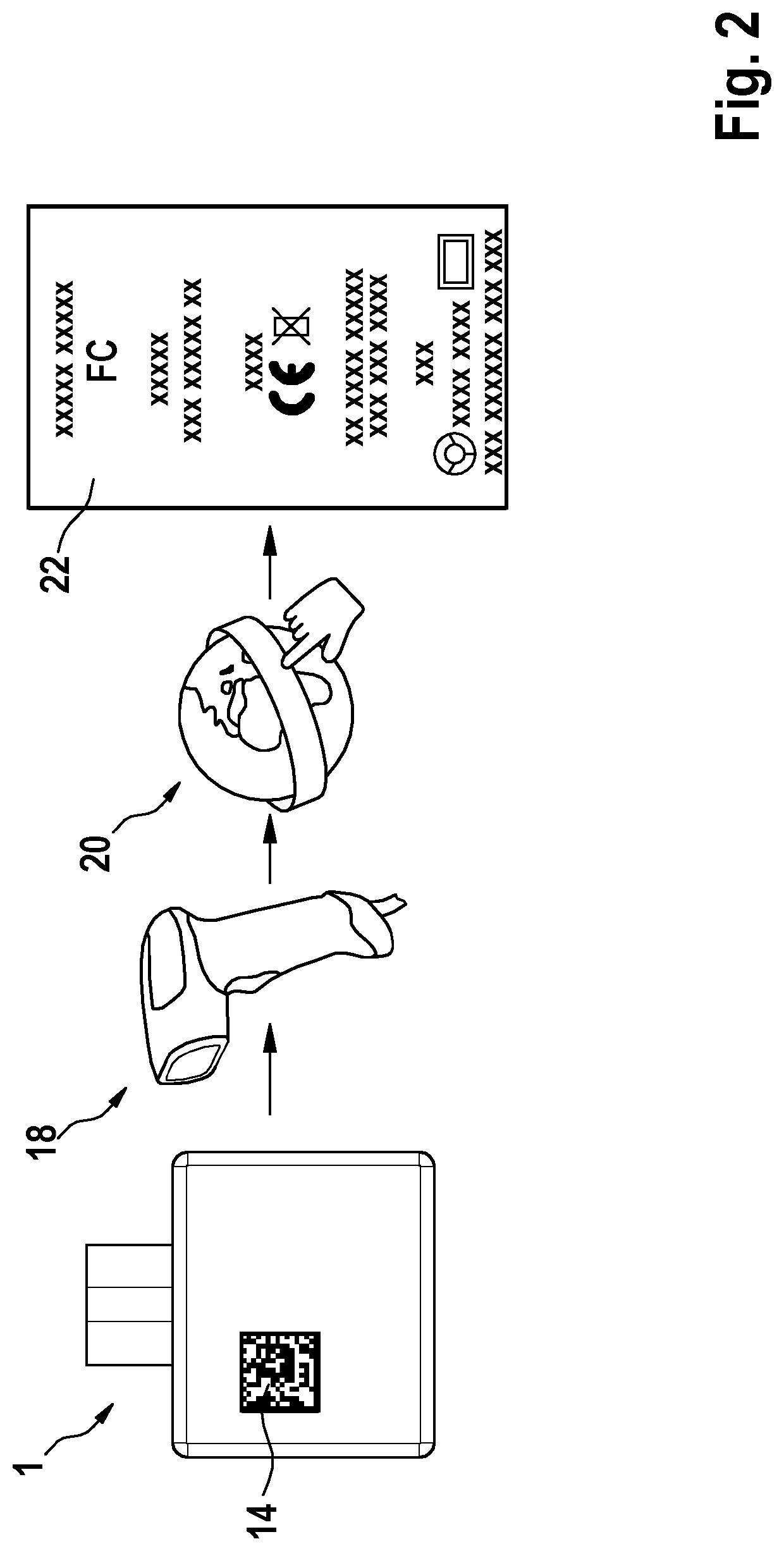
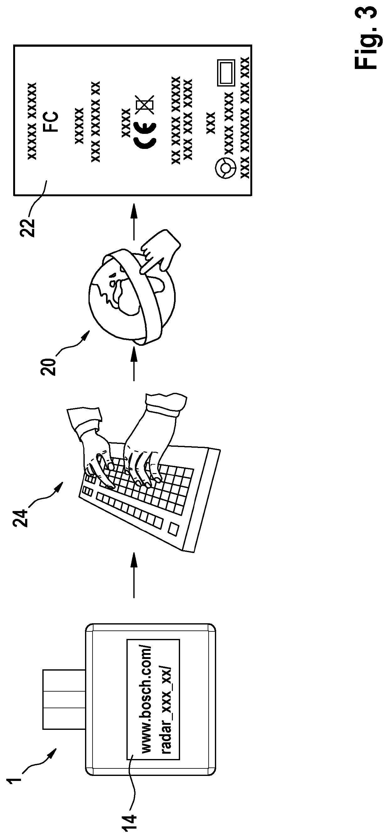
[0035]Component system 1 furthermore includes a communication element 14, 16. Communication element 14, 16 may be configured as a visible communication element 14 or as a non-visible communication element 16.

[0036]A visible communication element 14 may, for example, be situated on a first housing half 6. A non-visible communication elem...


PUM


Abstract

A method for providing markings, in particular, homologation markings, of a component, at least one communication element, which is situated on the component or integrated into the component, being read out visually, electronically or electromagnetically, at least one code being ascertained as a result of the read-out of the communication element, and the ascertained code being used for digitally retrieving and outputting the markings of the component. A component system is also described.

Description

CROSS REFERENCE[0001]The present application claims the benefit under 35 U.S.C. § 119 of German Patent Application No. DE 102019213774.1 filed on Sep. 10, 2019, which is expressly incorporated herein by reference in its entirety.FIELD[0002]The present invention relates to a method for providing markings, in particular, homologation markings, to a component, as well as to a component system.BACKGROUND INFORMATION[0003]As a result of vehicles being increasingly equipped with automation functions, safety functions and comfort functions, the number of installed components is on the rise. Such components may be sensors and control units, for example. Radar sensors are predominantly used to implement adaptive cruise control and emergency braking assistance systems, for example. The radar sensors emit high-frequency electromagnetic waves via an antenna structure, and receive the portions of the electromagnetic waves reflected at objects. With the aid of the received waves, it is possible t...

Claims


Application Information

Patent Timeline
Patent Type & Authority Applications(United States)
IPC IPC(8): G09F3/02G01S7/02
CPCG09F3/02G01S13/931G01S7/02G06K19/06037G06K19/07758G06K7/10861G06K7/10881G06K7/10386G06F16/9554G01S7/027G09F2003/0208
Inventor HOLLAENDER, CHRISTIANHILDEBRANDT, JUERGEN
Owner ROBERT BOSCH GMBH
Why Eureka
Try Eureka