Assistance and emergency backup for the electrical drive of a fuel pump in a turbine engine

a technology of electrical drive and turbine engine, which is applied in the direction of positive displacement liquid engine, pump, machine/engine, etc., can solve the problems of electric failure in flight on the electric motor, no means are provided for controlling the speed of the air turbine, and problems in vehicle piloting

Active Publication Date: 2011-03-01
SN DETUDE & DE CONSTR DE MOTEURS DAVIATION S N E C M A
View PDF7 Cites 7 Cited by
  • Summary
  • Abstract
  • Description
  • Claims
  • Application Information

AI Technical Summary

Benefits of technology

[0009]The object of this invention is to remedy the above-mentioned problem by means that are simple, improving the operation of the fuel pump drive system so as to increase the operating safety of the turbine engine in the event of a failure in the electrical system.
[0016]Thus, regulating the fluid feed to the assistance means can be used for bringing the turbine engine to the desired operating speed. More precisely, since the fluid feed is regulated by a regulator valve, i.e. a valve that is progressive (the extent to which the valve is opened can be varied continuously), the turbine engine can genuinely be maintained at the desired speed of rotation, thus making it possible in particular to avoid having to stop the turbine engine, as would be necessary if it were being fed with fuel in a manner that did not make it possible to take account of other operating parameters (airplane speed, air temperature and pressure, etc.).
[0018]This solution has the advantage of being technically very simple, since the rate at which fuel is delivered by the pump can be regulated merely by a regulator valve, and on the basis of one or more items of information that are commonly available in a flying vehicle, namely said information representative of the speed of rotation of the pump, and / or the speed of rotation of the turbine engine, and / or the fuel flow rate delivered to the turbine engine.
[0020]In particular, when the assistance means is an air turbine, it is possible to regulate the air turbine by modulating its air feed rate by means of a regulator valve such as a butterfly valve.

Problems solved by technology

Furthermore, in spite of the very great reliability of present-day electrical systems, it is always possible that an electrical failure will occur in flight on the electric motor driving the pump, or indeed on the electricity generator that powers the pump (the assembly constituted by one or more electric motors, and their electricity power supply means being referred to herein as the electrical system).
Unfortunately, no means are provided for controlling the speed of the air turbine.
That is why, under such circumstances, the air turbine, and consequently the fuel pump, are no longer under control, which can lead to problems in piloting the vehicle.

Method used


Image

  • Assistance and emergency backup for the electrical drive of a fuel pump in a turbine engine
  • Assistance and emergency backup for the electrical drive of a fuel pump in a turbine engine

Examples


Embodiment Construction

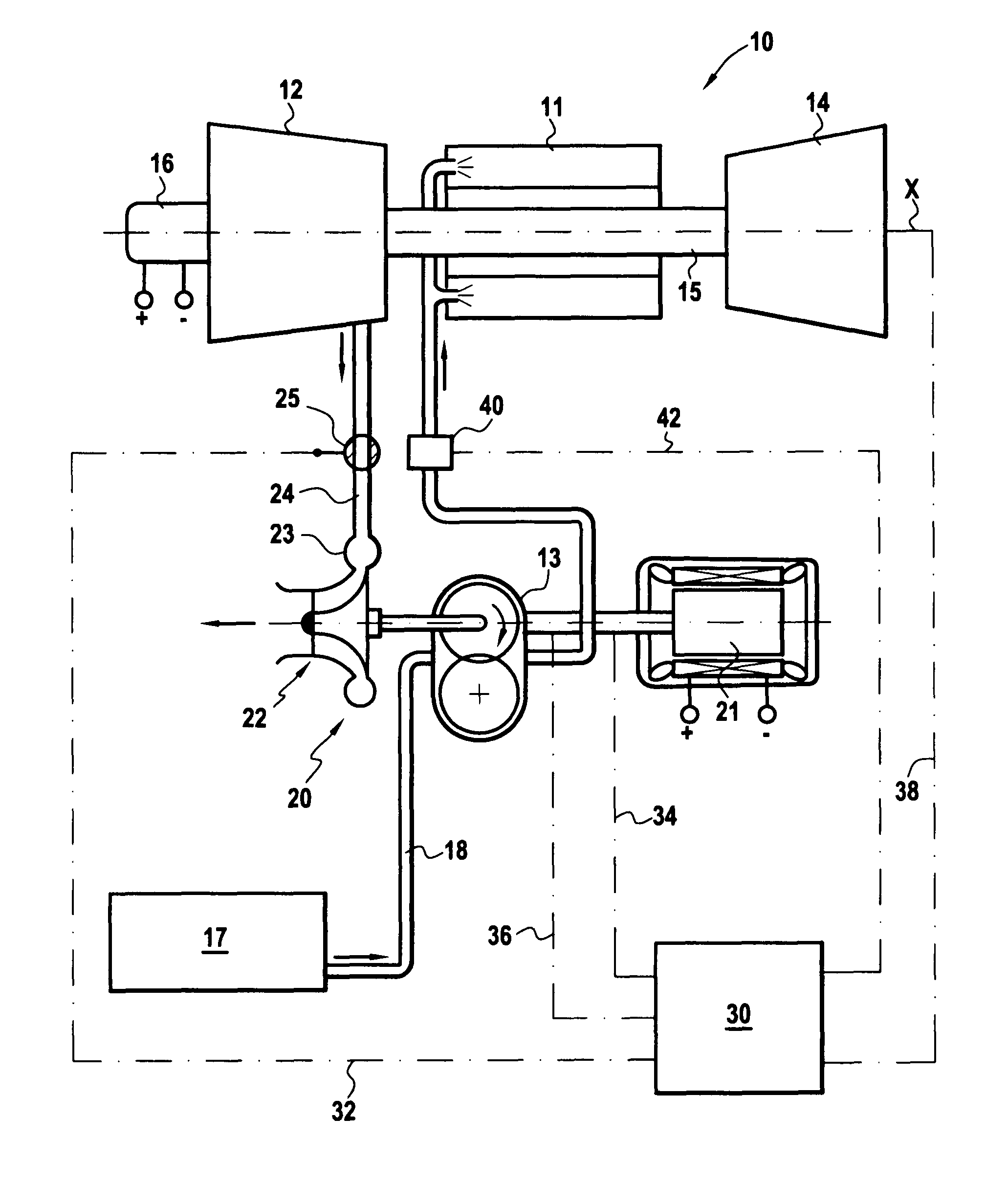
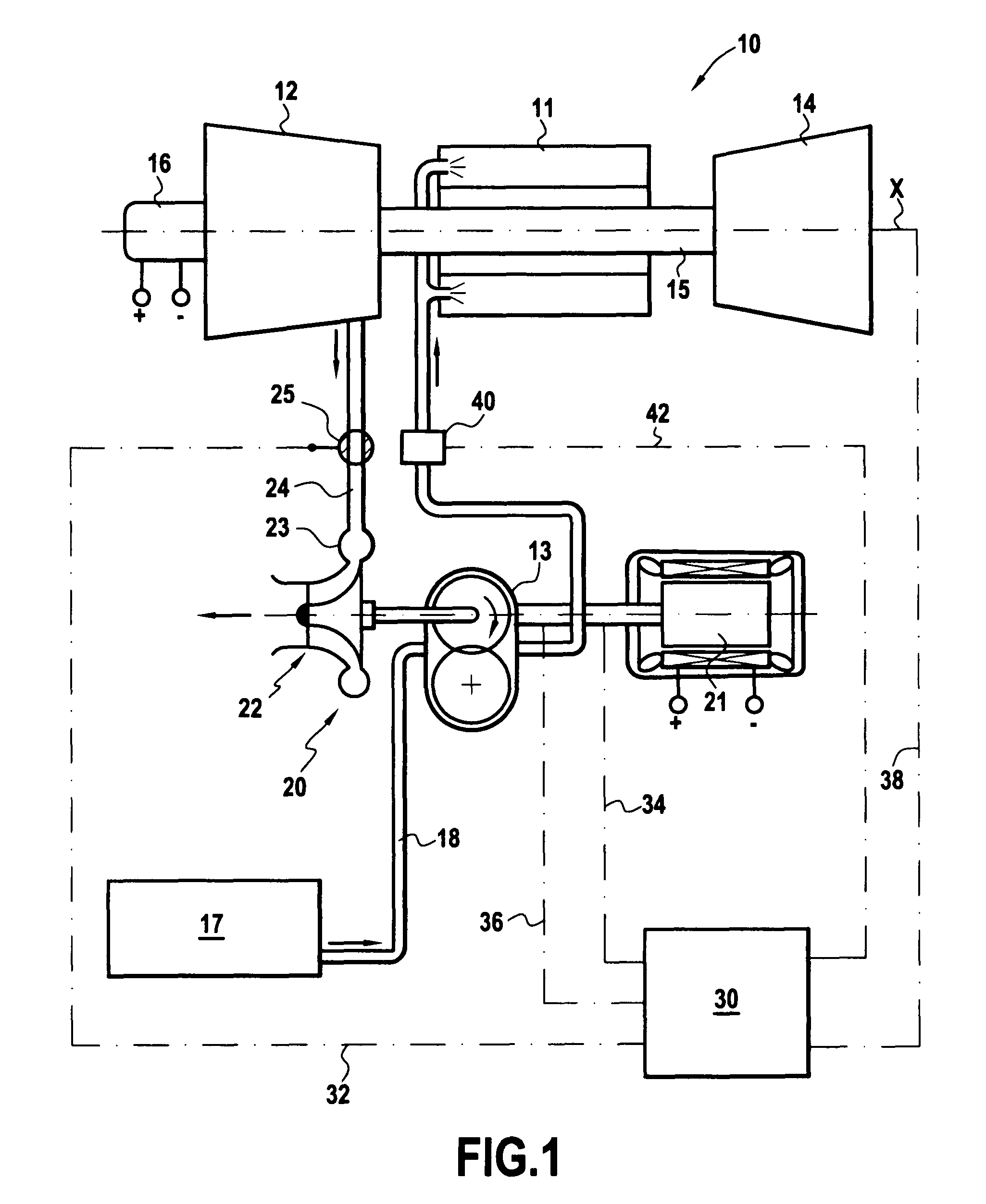
[0022]With reference to this figure, there follows a description of a turbine engine 10 of axis X and including a drive system of the invention for its fuel pump 13.

[0023]The turbine engine 10 is “all electric” and comprises a combustion chamber 11 fed with air by a compressor 12 and with fuel by a fuel pump 13. The hot gas coming from the combustion chamber 11 drives a turbine 14 that is connected to the compressor 12 by a shaft 15. The turbine engine 10 is also fitted with an incorporated starter-generator 16 on the axis X located in the cold zones of the compressor 12. Reference 17 designates a fuel tank that is connected to the pump 13 by a duct 18.

[0024]The fuel pump 13 is driven by a drive system 20 comprising firstly an electric motor 21 and secondly an air turbine 22 that is preferably on the same axis as the electric motor 21, having its inlet tube 23 connected to the compressor 12 by an air bleed duct 24 with a two-port regulator valve 25 interposed therein (i.e. a valve t...


PUM


Abstract

A system for driving a fuel pump in a turbine engine is disclosed. The system includes an electric motor and a fluid flow assistance unit controlled by a control valve. In the system, the control valve is a regulator valve the opening of which is controlled as a function of information representative of the speed of the pump, and / or the speed of the turbine engine, and / or the flow rate of fuel delivered to the turbine engine. As a result, operating safety of the turbine engine can be increased in the event of the electric motor failing or of its electricity generator failing, and the weight / size / cost ratios of the drive system are improved.

Description

[0001]The invention relates to operating safety in a turbine engine, in particular for an engine mounted on a flying vehicle and fed with fuel by a pump having a drive system that includes one or more electric motors. The invention also relates to optimizing such a drive system, and in particular it enables its weight / cost / size ratios to be improved.BACKGROUND OF THE INVENTION[0002]In such a drive system, the electric motor usually acts to regulate the flow rate of fuel, and no additional regulator is provided on the fuel feed line to the turbine engine, since that would be redundant.[0003]Furthermore, in spite of the very great reliability of present-day electrical systems, it is always possible that an electrical failure will occur in flight on the electric motor driving the pump, or indeed on the electricity generator that powers the pump (the assembly constituted by one or more electric motors, and their electricity power supply means being referred to herein as the electrical s...

Claims


Application Information

Patent Timeline
Patent Type & Authority Patents(United States)
IPC IPC(8): F02C9/00
CPCF01D15/08F02C6/08F02C7/22F02C7/32F05D2260/84Y02T50/671F05D2270/09F05D2270/304Y02T50/60
Inventor DELDALLE, REGIS MICHEL PAUL
Owner SN DETUDE & DE CONSTR DE MOTEURS DAVIATION S N E C M A
Why Eureka
Try Eureka