Coder and Decoder, Coding Method and Decoding Method, and System Comprising a Coder and a Decoder

a technology of coding method and decoding method, which is applied in the direction of coding, pulse conversion, digital transmission, etc., can solve the problems of no different potential levels being detected, error-prone transmission of digital signals, and complicated radio transmission over long distances

Inactive Publication Date: 2012-03-29
ATLAS ELEKTRONIC GMBH
View PDF31 Cites 6 Cited by
  • Summary
  • Abstract
  • Description
  • Claims
  • Application Information

AI Technical Summary

Benefits of technology

[0046]Only the number of code symbols corresponding to the number of different possible data symbols must be advantageously detected in the decoder. The mapping of the reception signal to the digital signal is thus bijective and can be implemented in a technically simple manner using a mirrored table of the table stored in the coder.
[0047]It is also advantageous that the decoder is designed to divide each data symbol into the same number of bits.
[0048]As a result of the fact that each data symbol comprises the same number of bits which is predetermined, the number of different data symbols is limited by the number of defined bits. The code symbols are accordingly also limited and the decoder must thus detect fewer different code symbols and can be implemented in a technically simpler manner.

Problems solved by technology

In this case, radio transmission over long distances is usually very complicated or even impossible on account of the attenuation properties.
When receiving this transmission signal received as a reception signal, the problem of no different potential levels being detected even though they have been produced arises in a decoder.
If the bit rate is thus intended to be increased on an electrical line above the maximum bit rate made possible by the non-return-to-zero method, for example, this results in error-prone transmission of the digital signal.

Method used


Image

  • Coder and Decoder, Coding Method and Decoding Method, and System Comprising a Coder and a Decoder
  • Coder and Decoder, Coding Method and Decoding Method, and System Comprising a Coder and a Decoder
  • Coder and Decoder, Coding Method and Decoding Method, and System Comprising a Coder and a Decoder

Examples


Embodiment Construction

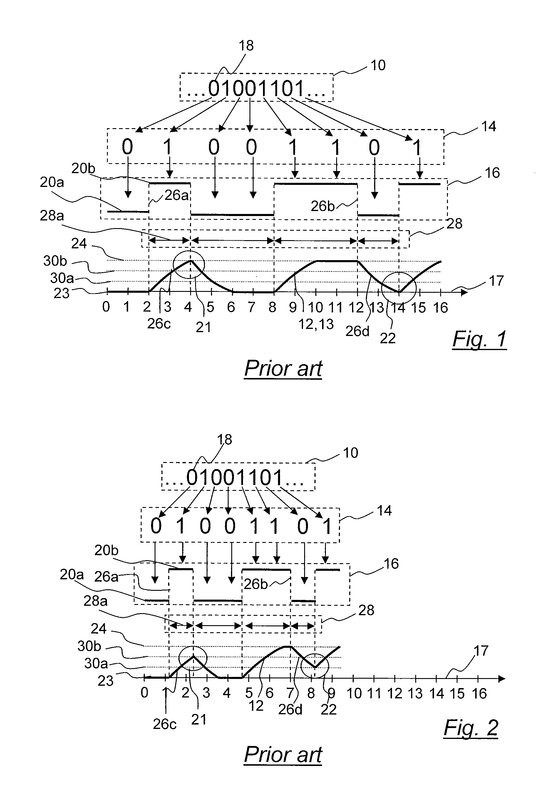
[0068]FIGS. 1 and 2 show a section of a digital signal 10 which is mapped to the transmission signal 12 for the case of coding using the known non-return-to-zero method. FIGS. 1 and 2 differ by virtue of the fact that different bit rates are respectively taken as a basis for transmission.

[0069]FIG. 1 shows a section of a digital signal 10 consisting of a bit string “01001101”, from which data symbols 14 are formed which are each allocated to the code symbols 16. A transmission signal 12 is generated from the code symbols 16 on the basis of the code symbols 16.

[0070]According to the known method, each data symbol 14 is formed from a bit 18 of the digital signal 10. Precisely two different data symbols 14 can be formed from the digital signal 10 according to the possible binary values of a bit 18. In the known method, the code space has one code symbol 16 for each data symbol 14, that is to say two different code symbols. One of the code symbols 16 has a low potential level 20a and th...


PUM


Abstract

A coder (36) for mapping a digital signal (10) into a transmission signal (12) and a decoder (44) for mapping a reception signal (13) into a digital signal (10) for transmission by and reception from a real channel (42), respectively. The coder (36) allocates code symbols (16) of a code space (40) to data symbols (14) of the digital signal (12) and generates the transmission signal (12) The decoder (44) detects the code symbols (16) on the basis of the reception signal (13) and allocates data symbols (14) of the digital signal (10) to the code symbols (16) of the code space (40). The data symbols (12) each have at least two bits (18) of the digital signal (10), and the code space (40) comprises code symbols (16) of two groups (38, 39).

Description

CROSS-REFERENCE TO RELATED APPLICATION[0001]The present application claims the priority of European patent Application No. 10400047.6, filed Sep. 25, 2010, the subject matter of which, in its entirety, is incorporated herein by reference.BACKGROUND OF THE INVENTION[0002]The invention relates to a coder for mapping a digital signal into a transmission signal and to a coding method for this purpose, and to a decoder for mapping a signal transmitted as a transmission signal and received as a reception signal into a digital signal and to a decoding method for this purpose. The invention also relates to a system comprising a coder for mapping a digital signal into a transmission signal and a decoder for mapping a signal transmitted as a transmission signal and received as a reception signal into a digital signal.[0003]In the field of signal transmission, digital signals are often transmitted at high data rates over long distances using long lines, for example electrical lines. One exampl...

Claims


Application Information

Patent Timeline
Patent Type & Authority Applications(United States)
IPC IPC(8): H04L27/00
CPCH03M5/08H03M13/00
Inventor SCHMIDT, EBERHARD
Owner ATLAS ELEKTRONIC GMBH
Why Eureka
Try Eureka