[0009]The present invention solves various performance problems associated with previous hose or tubing mounting designs. For example, damage or fracture of
thermoplastic materials resulting from installation bolt
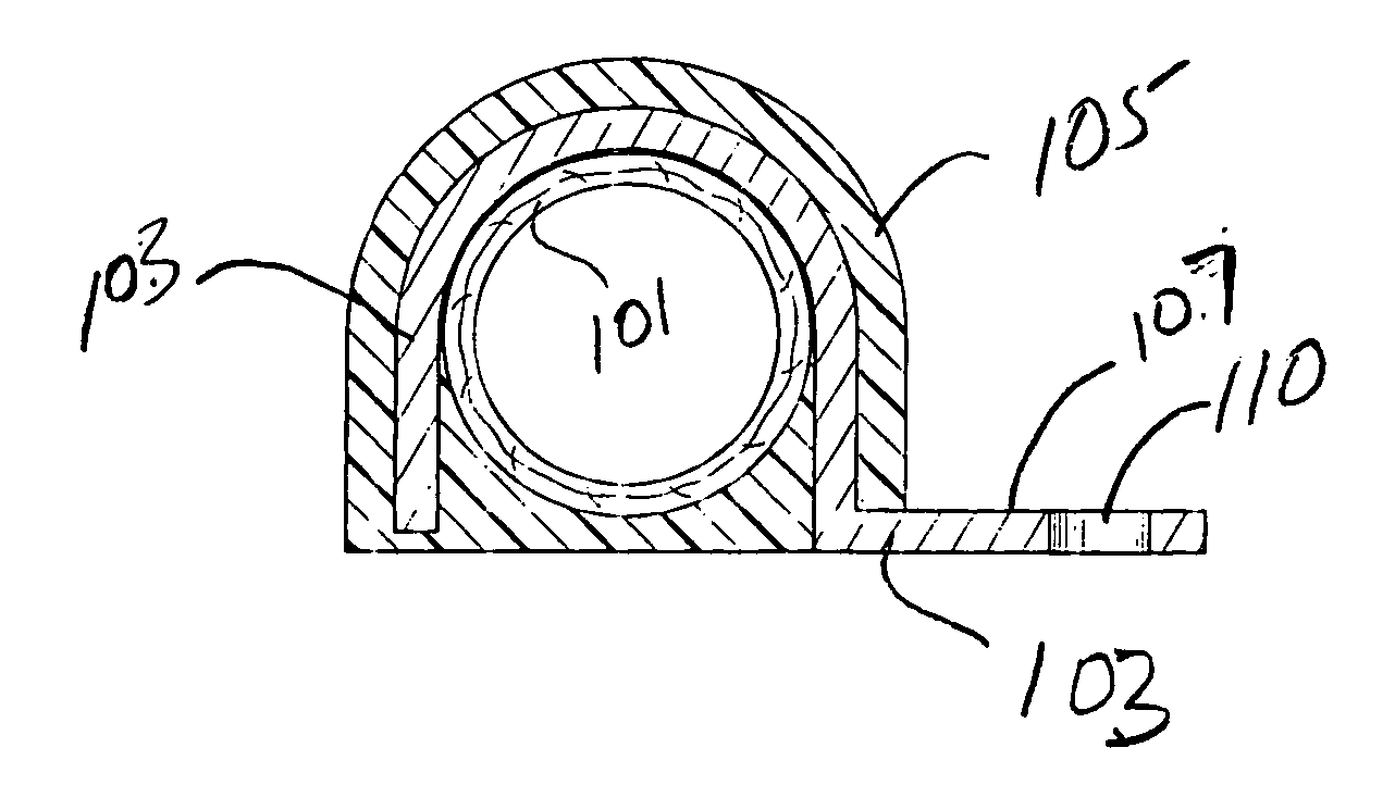
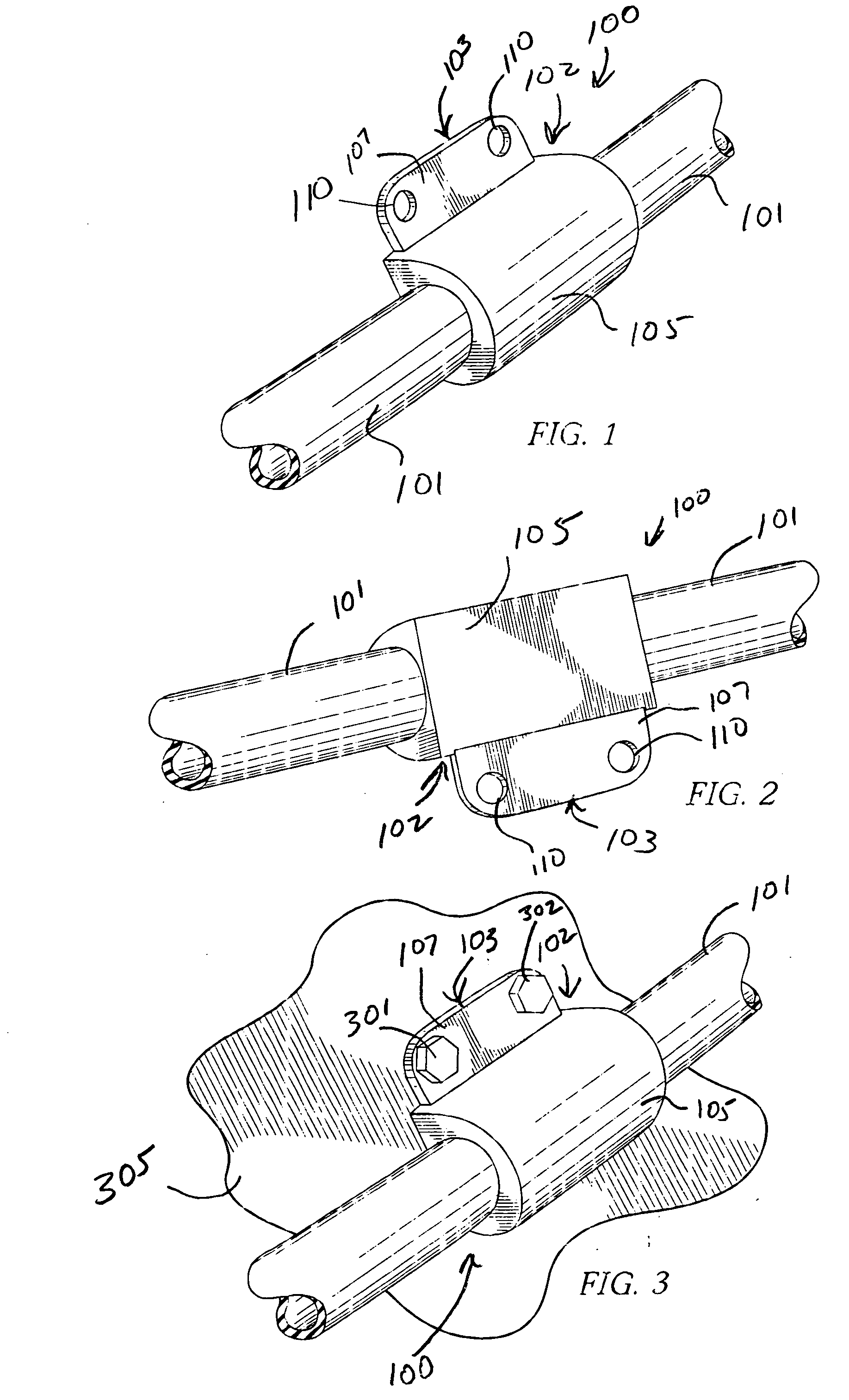
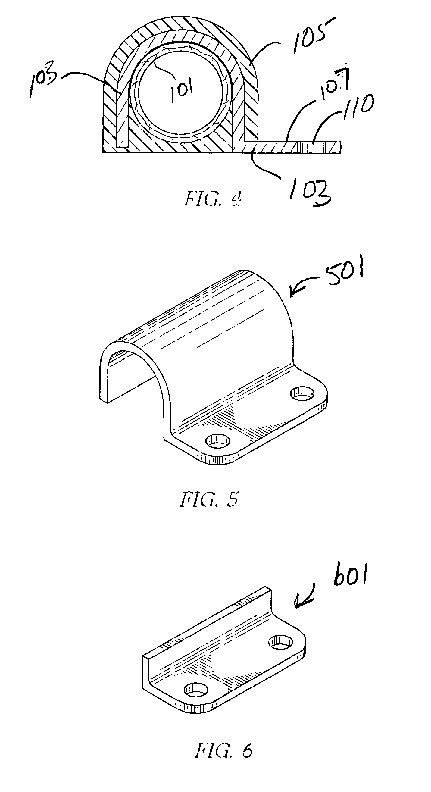
fastener forces may be addressed by embodiments of the present invention, wherein at least a portion of a rigid metal mounting bracket is not encapsulated by the overmold, particularly the portion of the mounting bracket that includes bolt holes or the like. As a result mounting bolts are allowed to bear on the exposed metal rather than on unreinforced resin or the like as is often the case in previous brackets. As a further example, the lack of adequate mechanical or
adhesive integrity of the hose component to an associated bracket is addressed in embodiments of the present invention by entirely overmolding the bracket and hose junction with a resin, or the like that can bond, mechanically, thermally and / or chemically with both the bracket and the hose or tube. Embodiments of the present invention also alleviate any need for elastomeric bushings or the like to be installed between hose components and metal brackets, as the present invention eliminates any relative movement between the bracket and the hose or tube. Additionally, an embodiment of the present invention can be employed in a hose assembly through a
single step, relatively low skill-level procedure. Hence, adoption of the present invention in hose assemblies can result in reduced complexity of components and a simplification of manufacturing processes leading to reduced manufacturing and installation costs.
[0010]The combination of the insert over mold and hose or tube through the present invention by insert molding, such as through the use of
pressure injection molding of the plastic overmold material, provides a robust assembly able to meet strenuous application and
system requirements. This
system robustness may be especially important in
heavy duty applications, such as large trucks and
heavy equipment. For example, a
metal insert described provides robustness to resistance of clamping torques and pressures at the mounting surfaces. Additionally, a
metal insert provides robustness to axial and rotational forces applied to the assembly resulting from
system requirements. Advantageously, embodiments that employ a
metal insert that partially encompasses the hose or tube can retain a hose or tube in place, at least to some degree, in the event that the over molded plastic material is damaged. Further, insert injection molding of the components is an economically efficient method of providing the function of the components in an assembly. As a further measure, the metal insert can contain cutaway portions and or reduced dimensions of thickness or area of the component resulting in weight savings. Preferably the overmolded plastic material provides an adjusted fit to both the hose and the metal insert components through controlled pressure molding of the material and by shrinkage of the material resulting from the molding process and shrinkage of the material after molding. Thereby, the overmolded material can provide radial forces capable of maintaining axial and rotational position on the hose preventing
abrasive damage to the hose component. As a further feature, the over molded material can contain
engraving or branding.
[0011]The over molded material can be disposed in such a manner to provide a mounting surface of the assembly to the system, including the aforesaid axial and radial positioning, as well as contact with system components such as frame members, while positioning the hose component away from direct contact with such system components. Additionally, the hose used in the assembly may contain a
textile or metal outer surface, a polymeric elastomeric outer surface, or combinations of these outer surfaces which can contribute to the robustness of the assembly to axial and rotational stresses.
[0013]Yet other embodiments of the present invention may include an assembly of one or more hoses or tubes, and an over molded plastic material which provides conformity of the hose to bends for routing the hose, with or without the use of a bracket insert associated with and / or encompassing a portion of some or all of the hoses and tubes. These embodiments provide connective bundling of two or more hoses or tubes in an assembly and may thereby provide environmental abrasion resistance and other advantages. Further, the use of a cured overmold that fuses, or at least mechanically bonds, to a surface of a hose through contraction of the overmold when it sets up to a relatively resilient rigidity can provide vacuum collapse resistance for a hose thus overmolded, and may provide
thermal protection for the hose.
[0015]Further, in accordance with any of the above embodiments, a thermoplastic material molded around a hose can be chosen to provide for protection of the hose against
abrasive damage to the hose from other components in the hose application environment and also chosen to provide
thermal insulation protection of the hose to the environment. Foamed Polyphenylene
Sulfide (PPS) sleeve might be a rigid, thermally protective sleeve material that could be used. Other embodiments might include ringed structures of overmolded thermoplastic material that adhere to the hose outside
diameter and which prevent vacuum collapse of the hose. Additionally such overmolded rings may serve the function to space a hose away from a structure and prevent abrasion of the hose against the structure.

