Cushion plate

Inactive Publication Date: 2005-12-01
NHK SPRING CO LTD +2
View PDF6 Cites 8 Cited by
  • Summary
  • Abstract
  • Description
  • Claims
  • Application Information

AI Technical Summary

Benefits of technology

[0011] Accordingly, It is an object of the present invention to provide a cushion plate having pawls an

Problems solved by technology

That is, the cushion plate may be abraded undesirably by friction with an adjacent member rotating relative to the cushion plate.
In other words, a relatively large stress concentration occur

Method used


Image

  • Cushion plate
  • Cushion plate
  • Cushion plate

Examples


Example

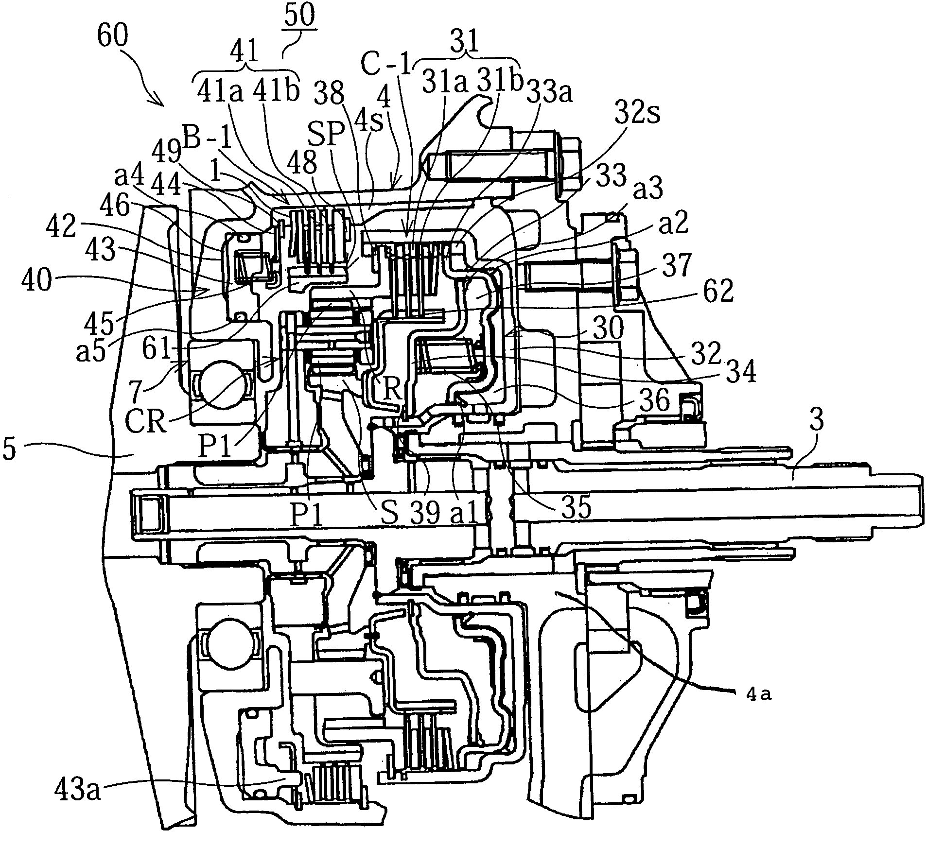
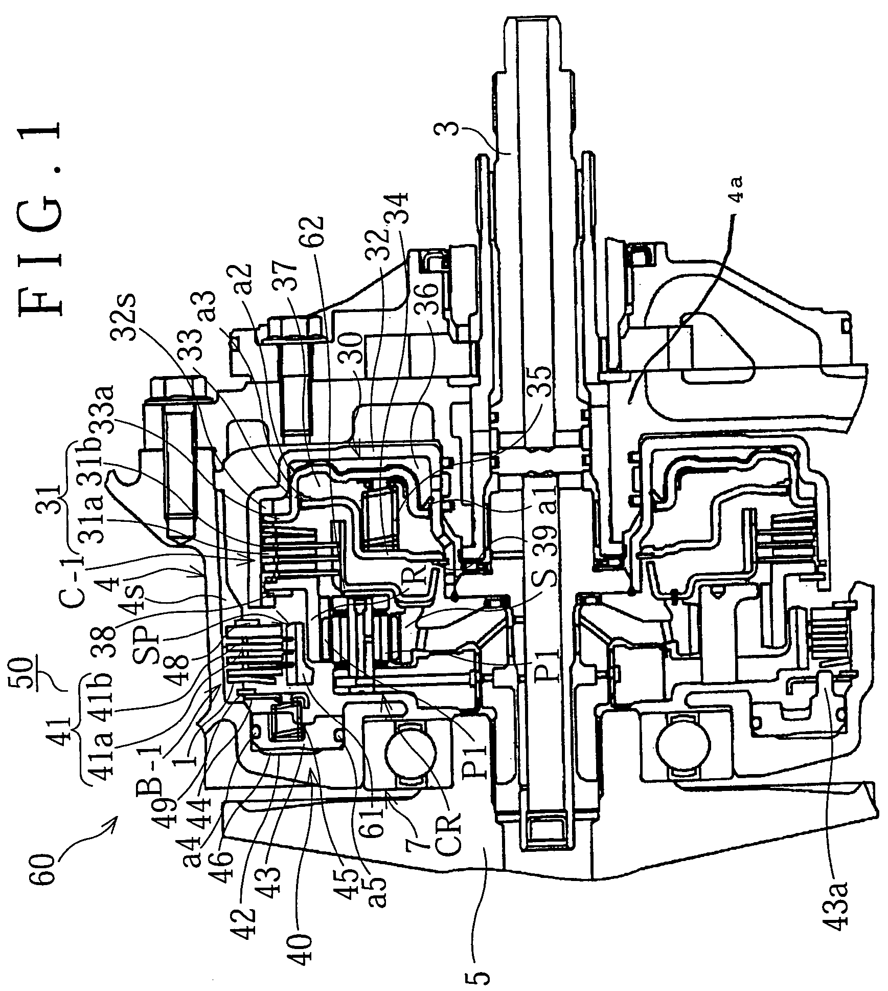
[0024] Hereinafter, an embodiment according to the present invention will be described with reference to the drawings. Firstly, an example of an automatic transmission to which the present invention is applied will be described briefly with reference to FIG. 1. As shown in FIG. 1, a belt-type continuously variable transmission (CVT) 50 is provided with, for example, an input shaft 3 and a pulley mechanism. Drive rotation is input from an engine to the input shaft 3 through a torque converter (not shown) or the like. The pulley mechanism includes a metal belt (not shown) held between a primary pulley 5 and a secondary pulley (not shown). The primary pulley 5 is supported by a transmission case 4 (a member on the outer periphery) through a ball bearing 7. The rotational speed of the primary pulley 5 is changed continuously by altering the pulley width, and the rotation as changed is output to the drive wheels through the secondary pulley. The belt-type CVT 50 has a forward / reverse swi...


PUM


Abstract

A cushion plate is provided, for example, between a piston of a hydraulic servo and an adjacent friction plate in a frictional engagement element of an automatic transmission. The cushion plate is deflected by a pressing force of the piston to absorb an engagement shock. The cushion plate includes a main body portion formed into a belleville-spring shape, and a plurality of pawls that extend from the outer periphery of the main body for spline engagement with a member that is splined to, for example, the friction plate. A side wall of each pawl is formed with a curved recess extending circumferentially of the cushion plate and located adjacent the juncture (base) of the pawl at the outer periphery of the main body.

Description

[0001] This application claims priority of Japanese Patent Application No. 2004-163896 filed Jun. 1, 2004. The disclosure of Japanese Patent Application No. 2004-163896 filed on Jun. 1, 2004 including the specification, drawings and abstract is incorporated herein by reference in its entirety. BACKGROUND OF THE INVENTION [0002] 1. Field of the Invention [0003] The present invention relates to a cushion plate used as a buffer in a multi-plate frictional engagement element provided in, for example, an automatic transmission of a vehicle. Specifically, the present invention relates to a cushion plate in which stress concentration is reduced when it is deflected. [0004] 2. Description of the Related Art [0005] Vehicular automatic transmissions utilize a multi-plate clutch or a multi-plate brake for changing a power transmission path within the transmission mechanism. In the multi-plate clutch or brake, movement of a piston of a hydraulic servo (actuator) is controlled based on the press...

Claims


Application Information

Patent Timeline
IPC IPC(8): F16D13/68F16D13/70F16D13/69F16D25/0638F16D25/12F16D55/40F16D65/12F16F7/08
CPCF16D13/683F16D25/12F16D25/0638F16D13/70
Inventor KITA, AKIHIKOTSUZUKI, SHIGEONOZAKI, HIROYUKIOGAWA, YUKITOSHIISHIKAWA, TAKAYUKI
Owner NHK SPRING CO LTD
Why Eureka
Try Eureka