Control apparatus and control method of generator for vehicle

a technology of control apparatus and control method, which is applied in the direction of electric generator control, dynamo-electric converter control, transportation and packaging, etc., can solve the problems of engine speed reduction, engine speed reduction, engine speed reduction, etc., to prevent engine speed reduction and timing belt abrasion, and suppress the drive torque of the generator

Active Publication Date: 2005-10-11
MITSUBISHI ELECTRIC CORP
View PDF15 Cites 8 Cited by
  • Summary
  • Abstract
  • Description
  • Claims
  • Application Information

AI Technical Summary

Benefits of technology

[0009]As a result, it is possible to suppress drive torque of the generator at cooling time and prevent engine speed from reduction and a timing belt from abrasion. Even in case of a generator without torque suppressing fu...

Problems solved by technology

It is a recent trend that various electrical components have been mounted on a vehicle and power consumption has been increased.
As a result, in the range of starting a high power type generator mounted on a vehicle at cooling time as well as idling operation, there is a possibility th...

Method used


Image

  • Control apparatus and control method of generator for vehicle
  • Control apparatus and control method of generator for vehicle
  • Control apparatus and control method of generator for vehicle

Examples


embodiment 1

[0014]A preferred embodiment of this invention is hereinafter described with reference to the drawings.

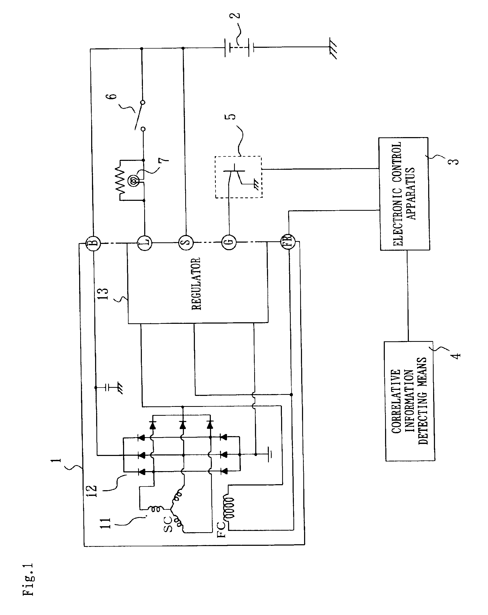
[0015]FIG. 1 is a circuit diagram showing a control system of a generator to which the invention is applied.

[0016]With reference to FIG. 1, a generator 1 is mainly comprised of a generating part 11 having a stationary coil SC and a field coil FC, a rectifier 12 formed of a diode, and a regulator 13. Among those elements, the regulator 13 changes a duty ratio of an exciting current flowing through the field coil FC in conformity with voltage of a buttery 2 and an electric load capacity actually used, thus regulating a current value generated by the generating part 11. That is, when the battery voltage decreases or the electric load capacity increases, the regulator 13 increases the duty ratio to increase the generated current and, under the adverse condition, decreases the duty ratio to decrease the generated current. The duty ratio FR of the exciting current flowing through the fie...


PUM


Abstract

An electronic control apparatus includes target FR calculator that calculates a target exciting current duty ratio FR based on an exciting current inputted from FR terminal of a regulator and flowing through field coil, and information of engine operating conditions. The electronic control apparatus also includes target FR limit value FRCLP calculator that calculates a FRCLP corresponding to a drive torque limit value based on an output of a correlative information detector. A comparator compares target FR and FRCLP, outputs a control signal within FRCLP to a control unit, and controls a duty ratio FR of exciting current flowing through a field coil not to be larger than FRCLP.

Description

BACKGROUND OF THE INVENTION[0001]1. Field of the Invention[0002]The present invention relates to a control apparatus of a generator for vehicle driven by rotation of an engine and to a control method of the generator.[0003]2. Description of the Related Art[0004]A vehicle such as automobile is generally provided with a generator driven by rotation force of a crankshaft of an engine in order to charge a battery acting as a power source with an electric power. In the case of decrease in battery voltage detected at a voltage detection terminal by a regulator or increase in capacity of an electric load, the generator increases a generated current by making larger a duty ratio of an exciting current inputted to a field coil. On the other hand, in the case of decrease in capacity of the electric load, the generator decreases a generated current by making smaller the duty ratio of the exciting current. Further, upper limit of the duty of the generated current can be set by a control signal ...

Claims


Application Information

Patent Timeline
IPC IPC(8): H02J7/22H02J7/16H02H7/06H02P11/00H02P9/10H02P9/00H02P7/06H02P9/14H02P9/30H02J7/24H02P9/48
CPCH02J7/244H02P9/48H02J7/243
Inventor FUJITA, YOSHITOMOYAMANE, KOICHINAKASHIMA, MASAMI
Owner MITSUBISHI ELECTRIC CORP
Why Eureka
Try Eureka