Control device and control method for a vehicle ac generator

Active Publication Date: 2013-12-19
MITSUBISHI ELECTRIC CORP
View PDF8 Cites 6 Cited by
  • Summary
  • Abstract
  • Description
  • Claims
  • Application Information

AI Technical Summary

Benefits of technology

[0006]The present invention has been made in order to solve the above-mentioned problem, and has an object to provide a control device and a control method for a vehicle AC generator, which are capable of suppressing drive torque in accordance with an RPM of the AC generator and improving energy efficiency and are also capable of reducing magnetic sound.
[0007]According to an exemplary embodiment of the present invention, there is provided a control device for a vehicle AC generator, the control device including: a power transistor for controlling conduction/non-conduction of a field coil in accordance with an output voltage of an AC generator mounted on a vehicle; an RPM detection section for detecting an RPM of the AC generator; a drive duty setting section for determining whether or not the RPM detected by the RPM detection section is equal to or higher than a predetermined threshold, and reducing a conduction ratio of the field coil when determining that the RPM is equal to or higher than the predetermined threshold; and a driver for driving th

Problems solved by technology

However, the suppression of the drive torque in accordance with th

Method used


Image

  • Control device and control method for a vehicle ac generator
  • Control device and control method for a vehicle ac generator
  • Control device and control method for a vehicle ac generator

Examples


first embodiment

[0017]A control device for a vehicle AC generator according to a first embodiment of the present invention is described below. Before the description, the principle of the present invention is described with reference to graphs of FIGS. 1 to 4.

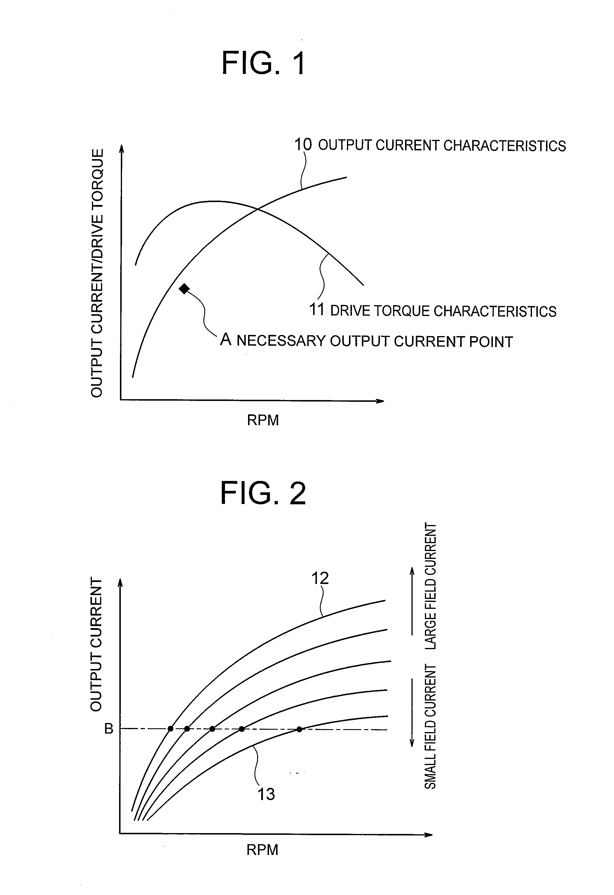
[0018]FIG. 1 shows a curve 10 and a curve 11 respectively representing typical characteristics of an output current and drive torque with respect to an RPM of an AC generator. The curve 10 and the curve 11 represent the characteristics for a field coil at full excitation. In FIG. 1, the vertical axis represents the output current and the drive torque of the AC generator, and the horizontal axis represents the RPM of the AC generator.

[0019]The point A of FIG. 1 indicates a point of electric power necessary for covering electric power for driving a plurality of electrical devices (electrical loads) mounted on a vehicle. As used herein, the point A is referred to as a necessary output current point whose coordinate is (Ax, Ay). The electric power...

second embodiment

[0054]A vehicle AC generator (AC generator 1) and a control device (regulator 5) therefor according to a second embodiment of the present invention have the same configurations as in FIG. 5. The second embodiment is different from the first embodiment in the operation of the drive duty setting section 510.

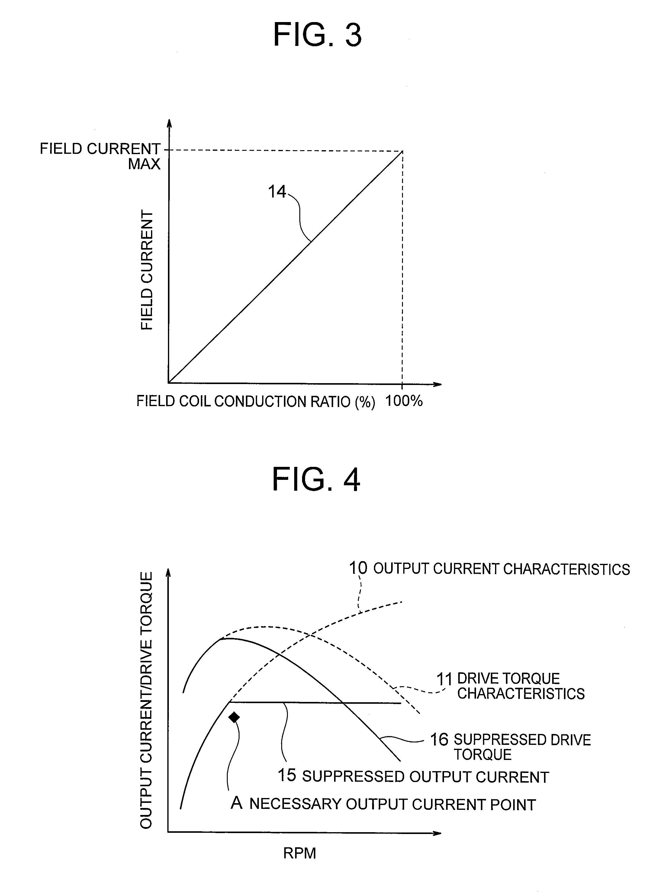
[0055]The first embodiment has described an example in which, when the RPM of the AC generator 1 has reached a predetermined value or higher, the drive duty setting section 510 switches the conduction ratio of the field coil 3 to a predetermined value lower than the current value. However, the RPM and the field current have the relationship shown in FIG. 2, and hence, when the drive duty setting section 510 is configured to switch the conduction ratios sequentially in accordance with the RPM, the magnitude of the output current can be controlled to the suppressed output current line represented by the solid line 15 of FIG. 4 more accurately. Specifically, the drive duty setting sec...

third embodiment

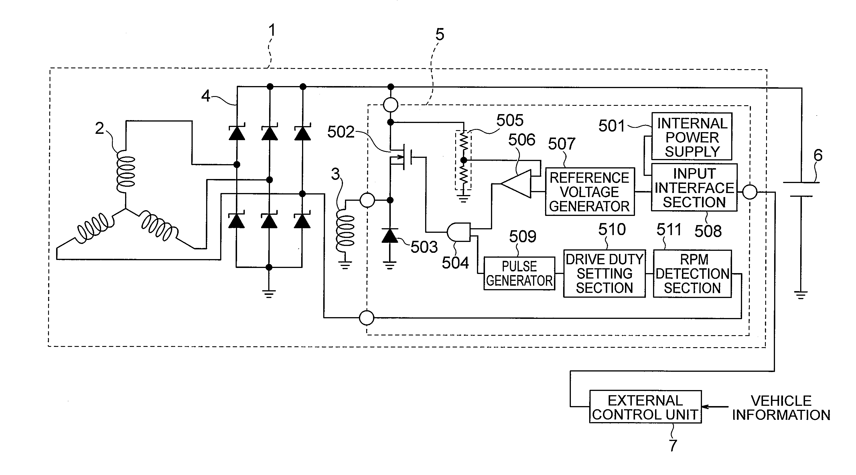
[0059]FIG. 6 is a diagram illustrating configurations of a vehicle AC generator (AC generator 1) and a control device (regulator 5) therefor according to a third embodiment of the present invention. As illustrated in FIG. 6, in the third embodiment, an input interface section 512 is provided instead of the input interface section 508 of FIG. 5. Further, a drive duty setting section 513 is provided instead of the drive duty setting section 510 of FIG. 5. In the third embodiment, the input interface section 512 is connected to the internal power supply 501 and the reference voltage generator 507 and also to the drive duty setting section 513. The other configurations are the same as in FIG. 5, and hence descriptions thereof are herein omitted. The operation different from the first embodiment is mainly described below.

[0060]The input interface section 508 in the first embodiment has the discrimination function of discriminating between two signals of the power supply activation signal...


PUM


Abstract

The control device including: a power transistor (502) for controlling conduction/non-conduction of a field coil (3) in accordance with an output voltage of an AC generator (1) mounted on a vehicle; an RPM detection section (511) for detecting an RPM of the AC generator (1); a drive duty setting section (510) for determining whether or not the RPM detected by the RPM detection section (511) is equal to or higher than a predetermined threshold, and reducing a conduction ratio of the field coil (3) when determining that the RPM is equal to or higher than the predetermined threshold; and a driver (504) for driving the power transistor (502) based on the conduction ratio. In this manner, the conduction ratio of the field coil (3) is reduced to suppress the drive torque.

Description

BACKGROUND OF THE INVENTION[0001]1. Field of the Invention[0002]The present invention relates to a control device and a control method for a vehicle AC generator, and more particularly, to a control device and a control method for a vehicle AC generator to be mounted on an automobile, for example.[0003]2. Description of the Related Art[0004]As described in Japanese Patent No. 2661613, for example, a conventional control device for a vehicle generator detects a temperature of the generator, and controls a field current to be supplied to a field coil in accordance with the detected temperature.[0005]In the conventional control device, electric power of the generator at low temperature can be adjusted to electric power thereof at high temperature, and drive torque of the generator at low temperature can be adjusted to drive torque thereof at high temperature. However, the suppression of the drive torque in accordance with the RPM (revolutions per minute) of the generator cannot be real...

Claims


Application Information

Patent Timeline
IPC IPC(8): H02P9/30B60L50/10
CPCH02P9/305H02P9/48
Inventor KOMURASAKI, KEIICHITANAKA, KAZUNORISUMIMOTO, KATSUYUKI
Owner MITSUBISHI ELECTRIC CORP
Why Eureka
Try Eureka