Adjustable mounting bracket for suspended ceiling

Active Publication Date: 2012-01-03
ARLINGTON INDS
View PDF9 Cites 17 Cited by
  • Summary
  • Abstract
  • Description
  • Claims
  • Application Information

AI Technical Summary

Benefits of technology

[0006]The load bearing assembly of the present invention includes features that simplify installation. A fastening arrangement provides an easy aligning feature for rapid fitting the assembly between two adjacent T-rails of an overhead grid system. A locking arrangement provides an easy method for adjusting the electrical box to any desired location between the T-rails. The combination of the fastening and locking arrangements of the load bearing assembly greatly simplify the task of installing an electrical box on a drop ceiling for the support of a lighting or fan fixture.
[0007]A further advantage is that superior load bearing ability is achieved by providing a center bracket that extends around substantially the entire outer periphery of the center bar. By utilizing a single center bar, simplicity is achieved over prior art bars that include three arms or two cross bars.
[0008]Substantially long end brackets and widely spaced support legs enable the load bearing assembly to better support lighting and fan fixtures against vibration and torque.
[0009]A further advantage is that the weight of a lighting or fan fixture is supported by structurally sound portions of the assembly, such as the center bracket, instead of being supported by the e

Problems solved by technology

Second, the electrical box is difficult to level as a result of the use of circular bars, a semicircular recess for accepting the first bar, the second bar being held between two parallel flanges, and foot mounts simply pressed onto the ends of the bars.
Any loosening of the central bolts could easily cause the electrical box to twist around one or both of the circular bars thereby throwing the electrical box out of a level orientation.

Method used


Image

  • Adjustable mounting bracket for suspended ceiling
  • Adjustable mounting bracket for suspended ceiling
  • Adjustable mounting bracket for suspended ceiling

Examples


Embodiment Construction

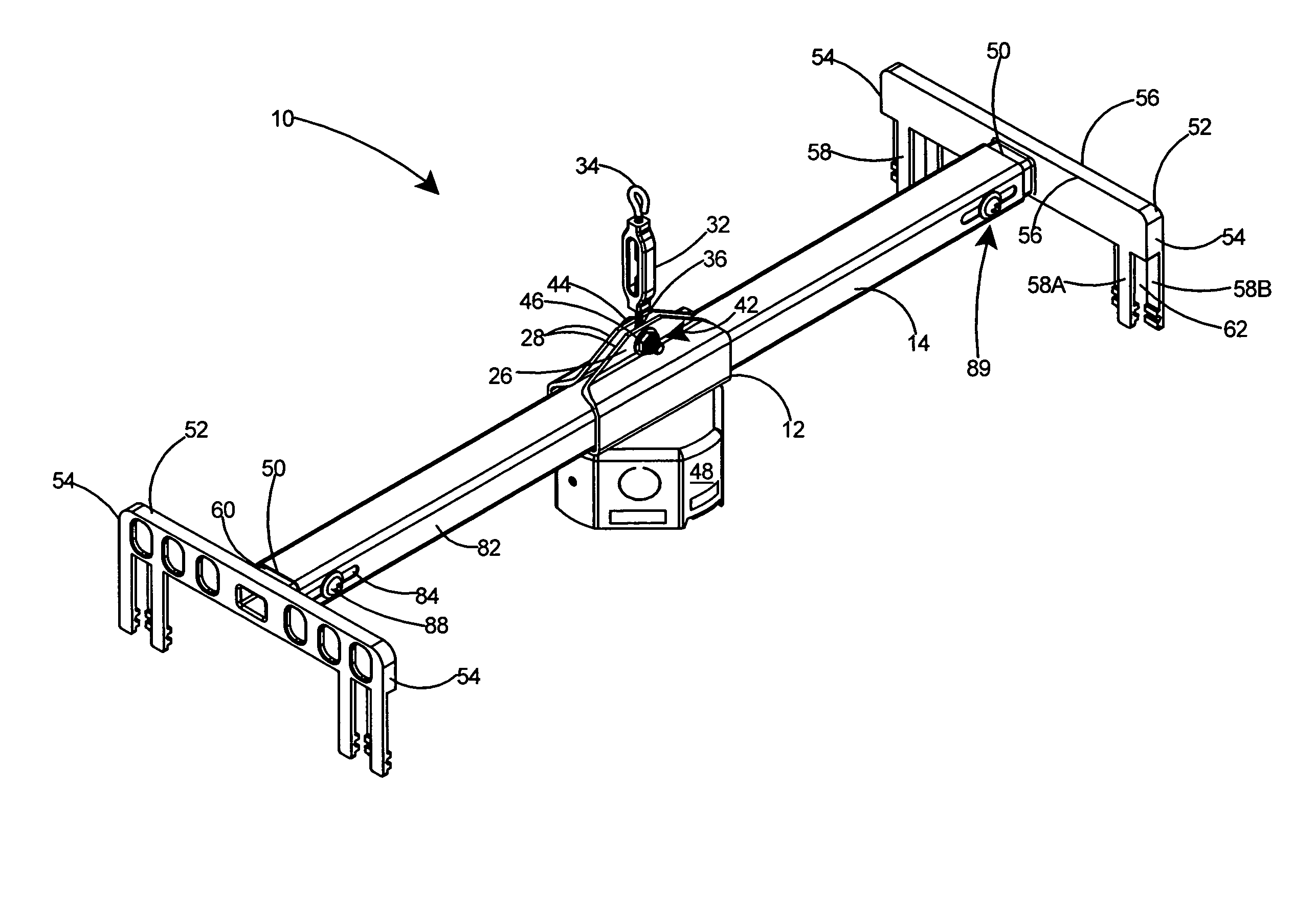
[0026]The present invention comprises a load bearing assembly for supporting a lighting or fan fixture on a drop ceiling.

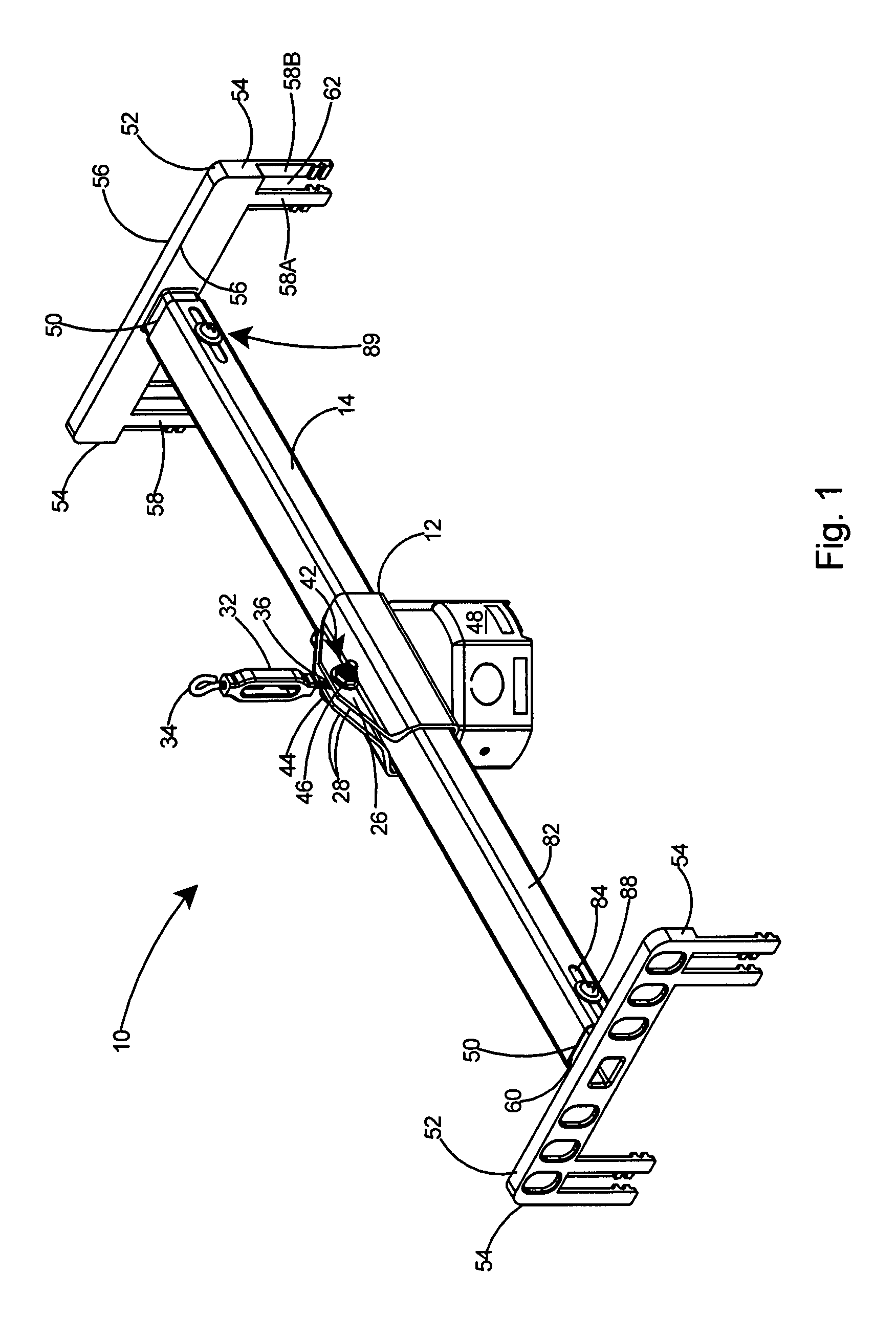
[0027]With reference to FIG. 1, a preferred embodiment of a load bearing assembly 10 includes a one-piece center bracket 12 and an elongated tubular bar 14. The elongated tubular bar 14 extends through the central channel 16.

[0028]Referring to FIG. 4, the center bracket 12 includes a central channel 16, a top portion 18, and a bottom portion 20. An opening 22 extends longitudinally along the top portion 18 of the center bracket 12 thereby forming two sides 24 at the opening 22. A wing 26 extends upward from each side 24 of the top portion 18 at the opening 22 thereby forming opposing wings 28 in opposing planes equidistant to one another. Each of the wings 28 includes an aperture 30, with the apertures 30 therein in axial alignment.

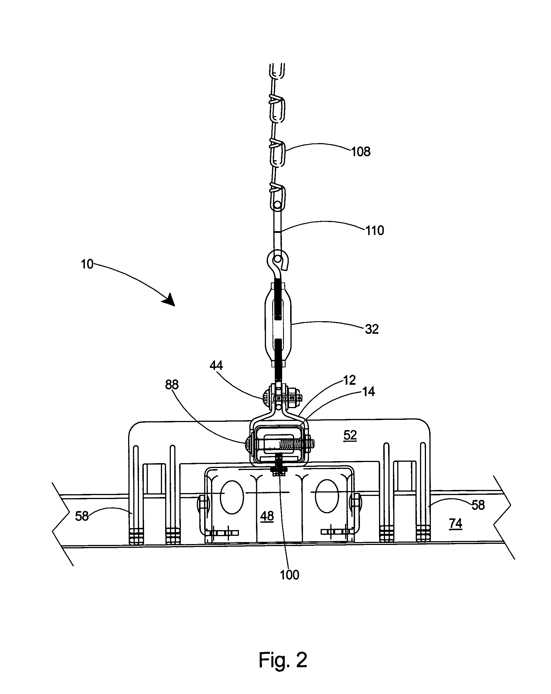
[0029]As shown in FIG. 1, a turnbuckle 32 having an upper end 34 and a lower end 36 is pivotally attached at its lower end 36 to the c...


PUM


Abstract

A load bearing assembly for supporting a lighting or fan fixture on a drop ceiling having a grid supporting structure. The assembly includes a single center bar, two end brackets with widely spaced support legs, and an electrical box. The support legs include removable portions that allow rapid modification to accommodate ceiling tiles of uniform thickness or ceiling tiles having a stepped edge. By adjusting the length of the legs, the lower surface of the tiles is leveled with the lower edge of the electrical box for either tiles of uniform thickness or those having stepped edges. A fastening arrangement enables adjustment of the end brackets with respect to the center bar, thereby allowing rapid fitting to adjacent T-rails. A locking arrangement enables easy adjustment of the location of the electrical box along the length of the center bar, thereby allowing the assembly to be rapidly fitted to a desired location on a drop ceiling.

Description

FIELD OF THE INVENTION[0001]This invention relates to load bearing hangers for overhead electrical boxes and specifically to an improved load bearing assembly that is easy to install and provides improved stability against vibration.BACKGROUND OF THE INVENTION[0002]Hanger assemblies are commonly used for supporting lighting or fan fixtures from drop ceilings. One such hanger assembly is shown in U.S. Pat. No. 5,435,514 issued to Kerr, Jr. The hanger assembly of Kerr, Jr. includes a first and second elongated and a bracket of an inverted U-shape configuration. The bracket includes a bottom wall with a transverse recess for receiving the first elongated bar and spaced apart flanges upstanding from the bottom wall for receiving the second elongated bar. Bolts through the bottom wall of the bracket secure the bracket to an electrical box and also sandwich the first bar between the transverse recess and the box. Another bolt extends transversely through the flanges and can be tightened t...

Claims


Application Information

Patent Timeline
IPC IPC(8): A47H1/10
CPCE04B9/006F21V21/049Y10S248/906
Inventor GRETZ, THOMAS J.
Owner ARLINGTON INDS
Why Eureka
Try Eureka