Head gimbal assembly, suspension for the head gimbal assembly, and disk drive unit with the same

a technology of head gimbal and suspension, which is applied in the direction of maintaining head carrier alignment, recording information storage, instruments, etc., can solve the problems of head flying height performance, read/write transducer damage, and become more and more difficult to quickly and accurately position the read/write transducer over the desired information tracks on the disk, etc., to achieve better operation performance

Inactive Publication Date: 2012-01-03
SAE MAGNETICS (HK) LTD
View PDF13 Cites 38 Cited by
  • Summary
  • Abstract
  • Description
  • Claims
  • Application Information

AI Technical Summary

Benefits of technology

[0009]Accordingly, one objective of the present invention is to provide a HGA which can prevent the read / write transducer thereof from damaged and gets better operation performance.
[0010]Another objective of the present invention is to provide a suspension for a HGA, which is capable of preventing the read / write transducer of a slider mounted thereon from damaged, and lower the gimbal stiffness and, in turn, gets better operation performance.
[0011]Another objective of the present invention is to provide a disk drive unit which prevents the read / write transducer from damaged and gets better operation performance.
[0034]In comparison with the prior art, the PZT element is formed at the leading edge of the substrate while the read / write transducer is formed at the trailing edge of the substrate, thus when the PZT element is driven, no potential voltage will be produced on the read / write transducer and the ESD problem will not happen, which accordingly protects the read / write transducer from damaged. Moreover, the electrical pads of the slider connect with the corresponding pads formed on the inner tongue, and the electrical leads are connected to the pads of the inner tongue along the curve beams. And the connecting points of the curve beams and the inner tongue being in mirror relations to a center point of the inner tongue, and the connecting points of each curve beam are located at opposite sides of a center axis of the flexure along a longitudinal direction thereof. When the PZT element is excitated, this structure generates a rotation torque and enables the slider rotating against its center, such that there is no force to transfer to suspension and no additional movement of the suspension excitated, to achieve a better positioning and resonance performance of the HGA and a desired servo bandwidth of the disk drive unit. Further, the curve beams serves as a hinge member, which can lower the gimbal stiffness such that the flying height of the slider can be adjusted more effectively. In addition, the leading edge of the outer tongue has a bonding pad formed thereon, and the bonding pad connects with the two bonding pads of the PZT element of the slider via an electrical bonding ball, causing the manufacture of the HGA simpler and the cost lower.

Problems solved by technology

As track density increases, it becomes more and more difficult to quickly and accurately position the read / write transducer over the desired information tracks on the disk.
However, as the PZT elements 22 and 141 are located adjacent to the read / write transducer in above-mentioned two approaches, the driving of the PZT elements will produce electrical charge and generate a potential voltage, which will make the read / write transducer damaged in case that, for example, ESD (electrical static discharge damage) problem happens.
And the deformation of the PZT elements are not only in head track direction but also in head fly height direction, which means when adjusting the read / write transducer for the position of the head track, the deformation will affect the head flying height performance, thus decreasing the dynamic performance of the slider.

Method used


Image

  • Head gimbal assembly, suspension for the head gimbal assembly, and disk drive unit with the same
  • Head gimbal assembly, suspension for the head gimbal assembly, and disk drive unit with the same
  • Head gimbal assembly, suspension for the head gimbal assembly, and disk drive unit with the same

Examples


Embodiment Construction

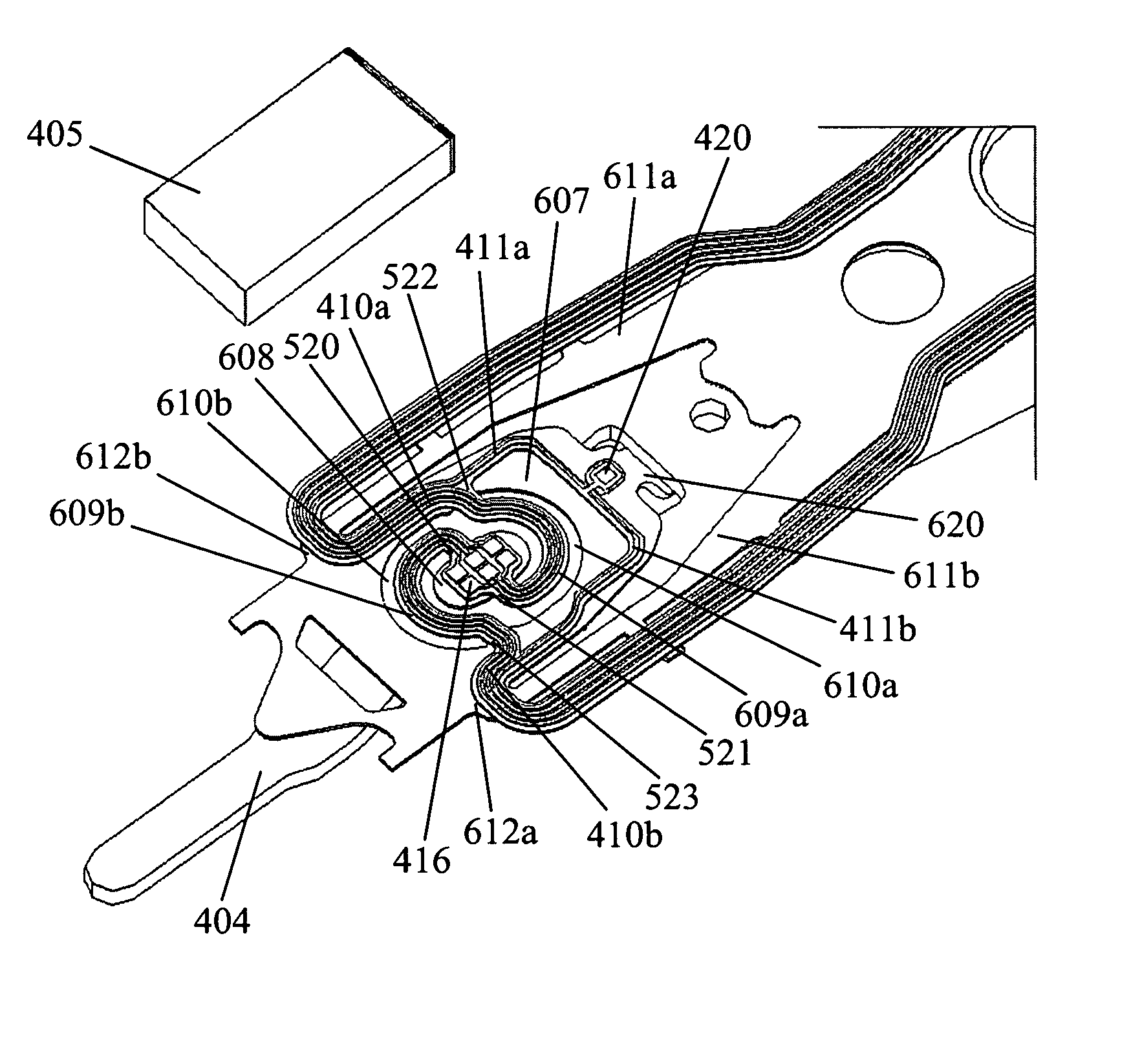
[0054]Various preferred embodiments of the invention will now be described with reference to the figures, wherein like reference numerals designate similar parts throughout the various views. As indicated above, the invention is directed to a HGA which includes a slider having a read / write transducer and a piezoelectric element formed oppositely, such that the HGA can prevent the potential voltage producing on the read / write transducer to protect the magnetic read / write transducer from damaged by the ESD problem and has better performance for positioning the slider.

[0055]FIGS. 4a-4c illustrates an embodiment of a HGA 400 of the present invention. Referring to FIG. 4a, the HGA 400 generally includes a slider 405 having a read / write transducer 501 (referring to FIG. 6a) imbedded therein, and a suspension 430 for loading or suspending the slider 405 thereon. As illustrated, the suspension 430 includes a base plate 401, a hinge 402, a flexure 403 and a load beam 404, all of which are as...


PUM

PropertyMeasurementUnit
widthaaaaaaaaaa
shapeaaaaaaaaaa
recording densityaaaaaaaaaa

Abstract

A HGA comprises a slider and a suspension with a flexure having a tongue region for supporting the slider. A read / write transducer and a piezoelectric element are formed oppositely. The connecting points of the curve beams and the inner tongue of the tongue region are in mirror positions to a center point of the inner tongue, and the connecting points of each curve beam are located at opposite sides of a center axis of the flexure. The slider has multiple electrical pads electrically connecting with the read / write transducer. The inner tongue has multiple electrical pads. The flexure has multiple inner leads electrically connected with the electrical pads of the inner tongue formed on the curve beams. The structure of the HGA prevents the read / write transducer from damaged and cause the manufacture of the HGA simpler. The present invention also discloses a suspension and a disk drive unit.

Description

FIELD OF THE INVENTION[0001]The present invention relates to an information recording disk drive device, and more particularly, to a head gimbal assembly (HGA), suspension for the HGA, and disk drive unit with the same.BACKGROUND OF THE INVENTION[0002]Hard disk drive incorporating rotating magnetic disks is commonly used for storing data in the magnetic media formed on the disk surfaces, and a movable read / write transducer is then used to read data from or write to the tracks on the disk surfaces.[0003]As consumers constantly desiring greater storage capacity for such disk drive devices, as well as faster and more accurate reading and writing operations, different methods are used to improve the recording density of information recording disk drive unit. As track density increases, it becomes more and more difficult to quickly and accurately position the read / write transducer over the desired information tracks on the disk. Thus, disk drive manufacturers are constantly seeking ways ...

Claims


Application Information

Patent Timeline
Patent Type & Authority Patents(United States)
IPC IPC(8): G11B5/48
CPCG11B5/4853
Inventor YAO, MINGGAOYAMANOI, KOYU
Owner SAE MAGNETICS (HK) LTD
Why Eureka
Try Eureka