Light-emitting fan

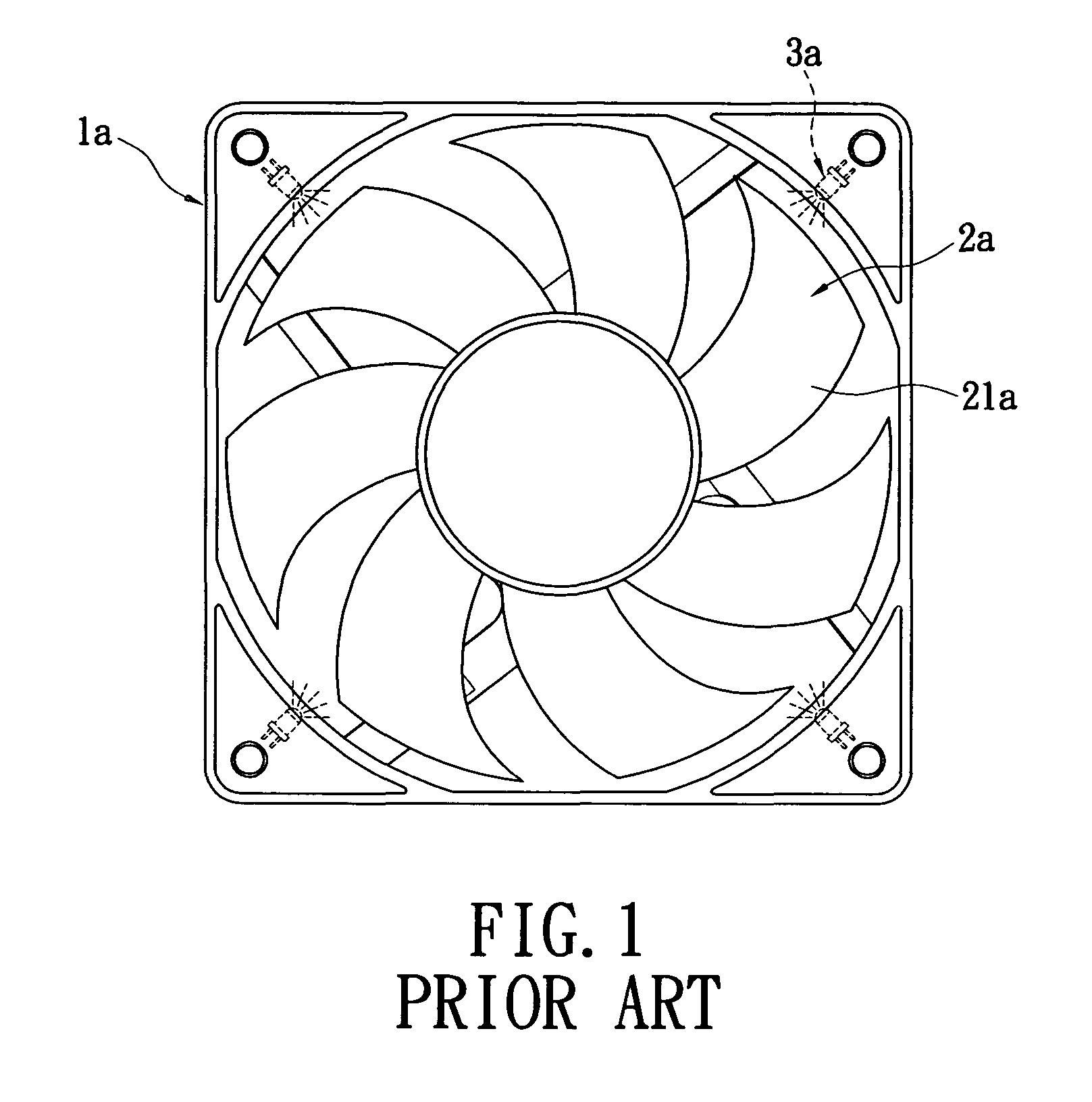
a fan and light-emitting technology, applied in the field of fans, can solve the problems of increased difficulty in manufacturing the frame la and inconvenient assembly of the fan

Active Publication Date: 2012-01-10
ENERMAX TECHNOLOGY CORPORATION
View PDF3 Cites 11 Cited by
  • Summary
  • Abstract
  • Description
  • Claims
  • Application Information

AI Technical Summary

Benefits of technology

[0007]The object of the present invention is to provide a light-emitting fan. A frame is provided therein with a flexible circuit structure, so that light-emitting elements can be combined with the frame easily via the flexible circuit structure.
[0009]The present invention has advantageous features as follows. In the light-emitting fan of the present invention, a plurality of light-emitting elements is provided on the flexible circuit structure, and the flexible circuit structure is combined on the frame. Therefore, the light-emitting elements can be combined to the frame more easily. In this way, the whole construction of the fan is simplified, so that it is easier to manufacture and assemble the fan.

Problems solved by technology

As a result, the difficulty in manufacturing the frame la is increased, and it is inconvenient to assemble the fan.

Method used


Image

  • Light-emitting fan
  • Light-emitting fan
  • Light-emitting fan

Examples


Embodiment Construction

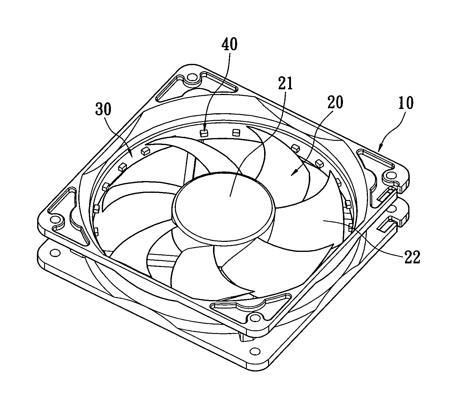
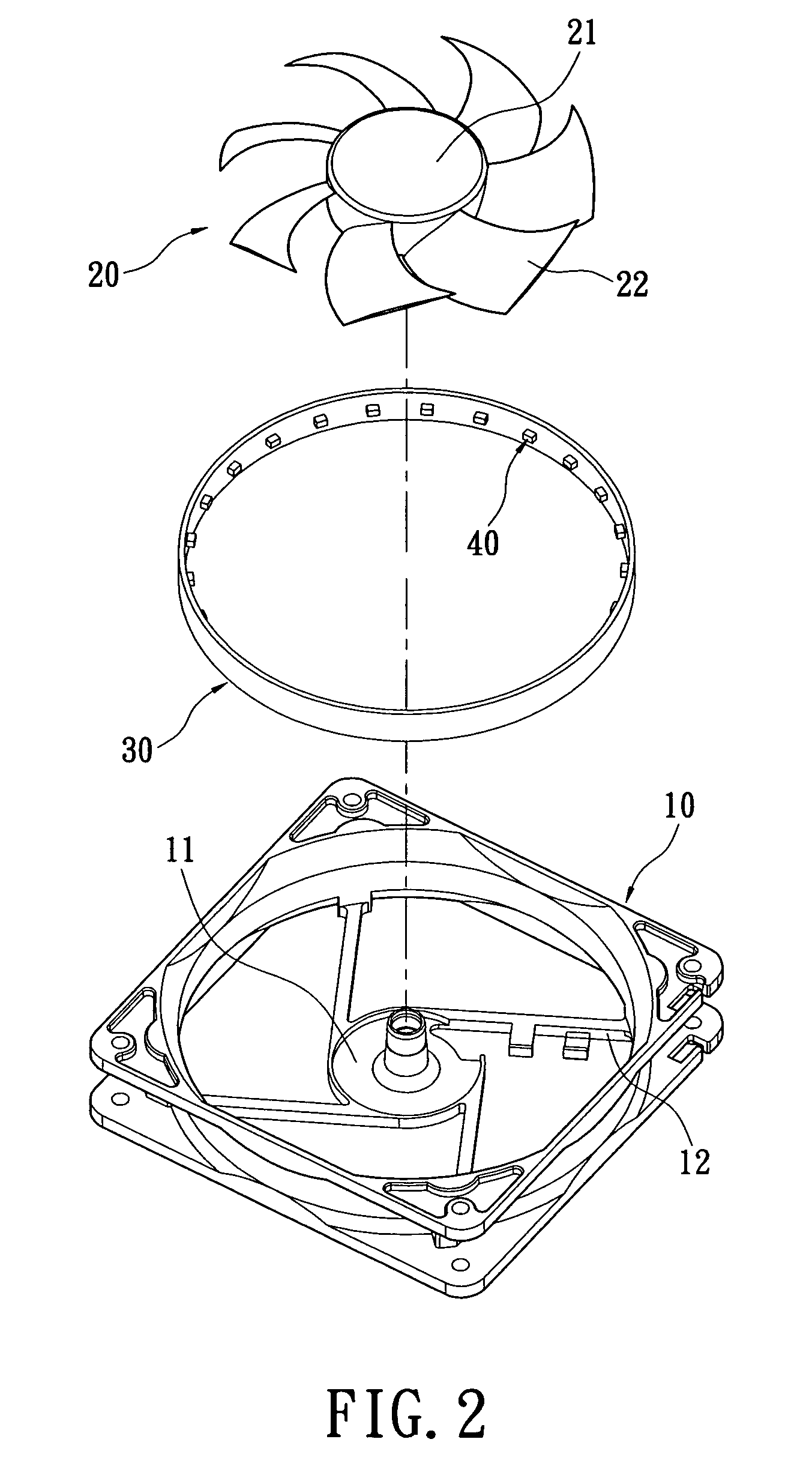
[0022]Please refer to FIGS. 2 and 3. The first embodiment of the present invention provides a light-emitting fan, which includes a frame 10, a vane 20, a flexible circuit structure 30, and a plurality of first light-emitting elements 40. The center of the frame 10 is provided with a base 11 and a plurality of ribs 12 connected with the base 11.

[0023]The vane 20 has a hub 21 and a plurality of blades 22. The blades 22 are connected to the periphery of the hub 21 at intervals. The vane 20 is pivotally provided to the base 11 of the frame 10 via the hub 21.

[0024]In the present embodiment, the flexible circuit structure 30 is a flexible printed circuit board and encircles to form a ring, but it is not limited thereto. The flexible circuit structure 30 is provided in the inner edge of the frame 10. The way of combining the flexible circuit structure 30 with the frame 10 is not limited to a specific one, and various suitable means can be used, such as adhering, via screws, locking, or the...


PUM


Abstract

A light-emitting fan includes a frame, a vane, at least one flexible circuit structures, and a plurality of light-emitting elements. The van is pivotally provided on the frame. The van has a hub and a plurality of blades connected to the hub. The flexible circuit structure is circumferentially provided on the frame. The light-emitting elements are provided on the flexible circuit structure to emit light respectively. With the above arrangement, the light-emitting elements can be combined with the frame easily via the flexible circuit structure.

Description

BACKGROUND OF THE INVENTION[0001]1. Field of the Invention[0002]The present invention relates to a fan, and in particular to a light-emitting fan in which a flexible circuit structure is combined with light-emitting elements to emit light via the light-emitting elements.[0003]2. Description of Related Art[0004]Please refer to FIG. 1. A conventional light-emitting fan includes a frame 1a. The center of the frame 1a is pivotally provided with a vane 2a having a plurality of blades 21a. Four corners of the frame la are provided with a light-emitting diode 3a respectively, so that the four light-emitting diodes 3a can emit light.[0005]However, when the light-emitting diodes 3a are mounted in the above-mentioned light-emitting fan, the frame 1a has to be additionally formed with a structure for mounting the light-emitting diodes 3a (such as mounting holes). Furthermore, leads (not shown) are used to connect the light-emitting diodes. As a result, the difficulty in manufacturing the frame...

Claims


Application Information

Patent Timeline
Patent Type & Authority Patents(United States)
IPC IPC(8): F04D29/00
CPCF04D25/0613F04D29/526F04D29/005
Inventor TSEN, CHIH-CHUN
Owner ENERMAX TECHNOLOGY CORPORATION
Why Eureka
Try Eureka