Battery connector

a battery connector and connector technology, applied in the direction of coupling contact members, coupling device connections, electric discharge lamps, etc., can solve the problems of difficult to make the soldering portion soldered to the printed circuit board successfully, and the difficulty of locating the battery connector firmly and precisely, so as to increase the supporting area and fasten the insulating housing

Inactive Publication Date: 2012-01-10
CHENG UEI PRECISION IND CO LTD
View PDF10 Cites 19 Cited by
  • Summary
  • Abstract
  • Description
  • Claims
  • Application Information

AI Technical Summary

Benefits of technology

[0008]As described above, when the battery connector is assembled to the printed circuit board, the locating pieces of the insulating housing press against the printed circuit board to increase a supporting area of the insulating housing on the printed circuit board so as to make the battery connector located on the printed circuit board firmly, and the holding pieces of the holding elements are inserted into the printed circuit board to fasten the insulating housing on the printed circuit board accurately. So that the soldering portions of the terminals can be conveniently soldered to the printed circuit board.

Problems solved by technology

However, in a process of mounting the battery connector to the printed circuit board, a relative movement between the battery connector and the printed circuit board may occasionally happen, so that causes the difficulty of locating the battery connector firmly and exactly.
As a result, it is hard to make the soldering portion soldered to the printed circuit board successfully.

Method used


Image

  • Battery connector
  • Battery connector
  • Battery connector

Examples


Embodiment Construction

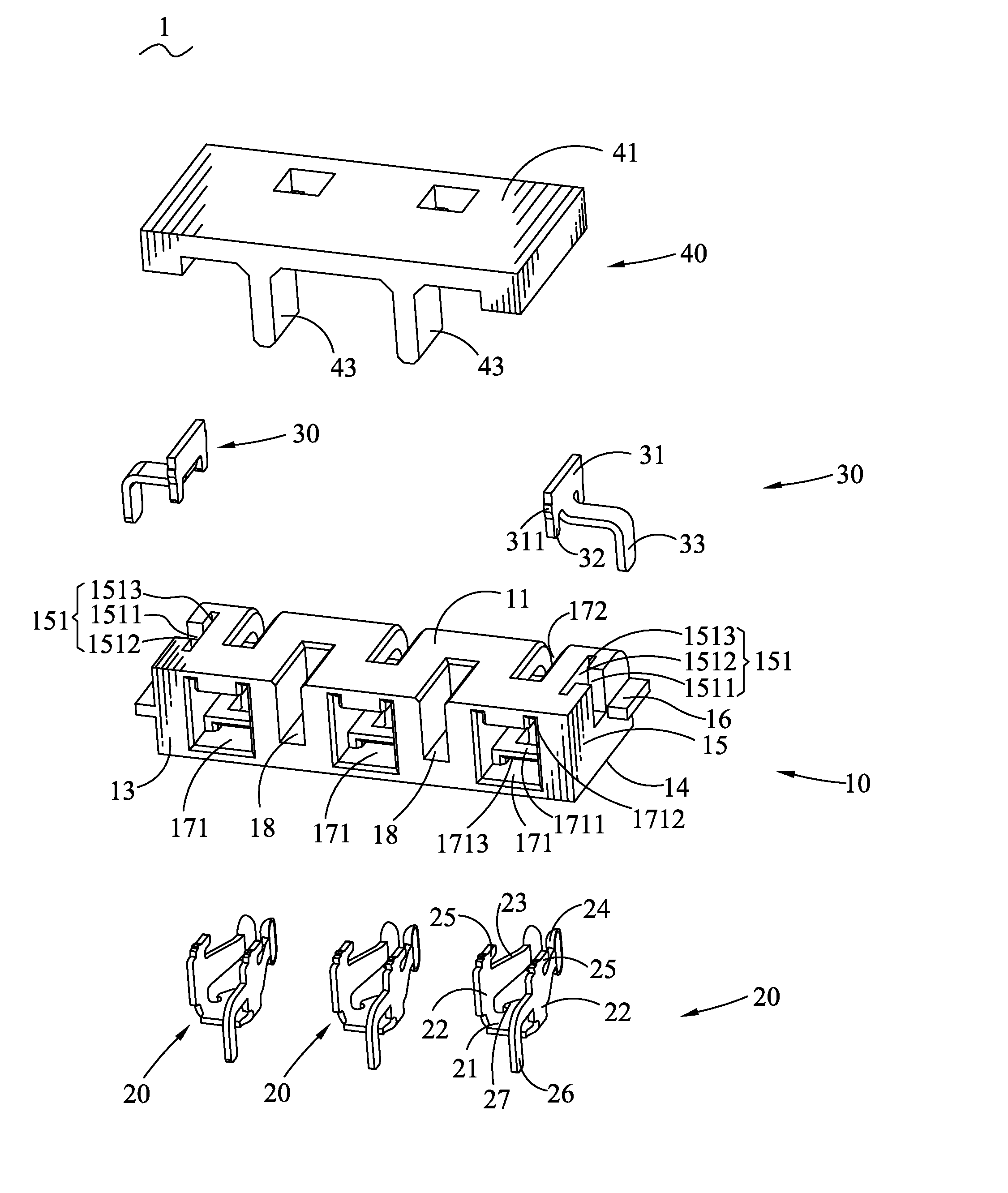
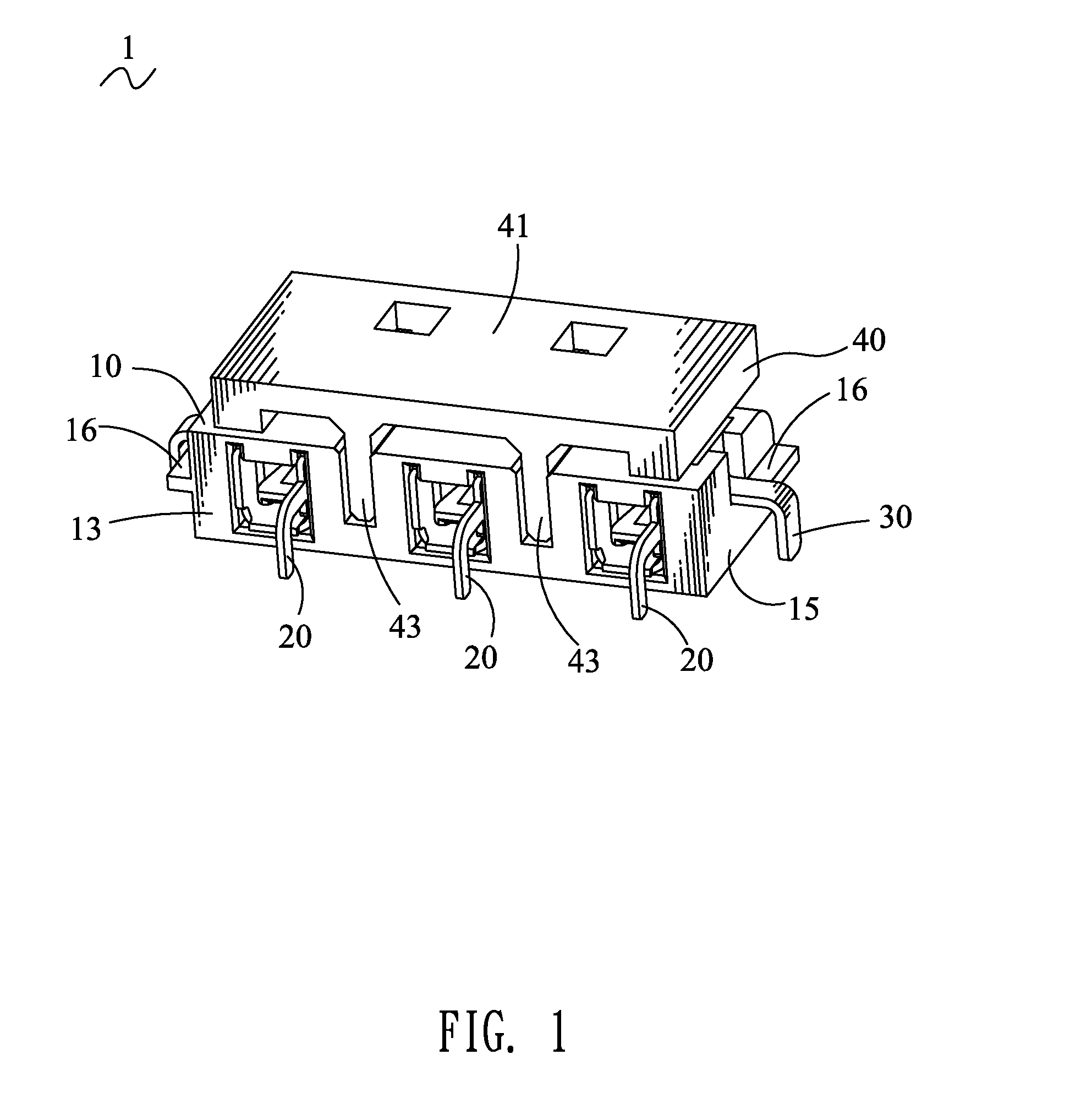
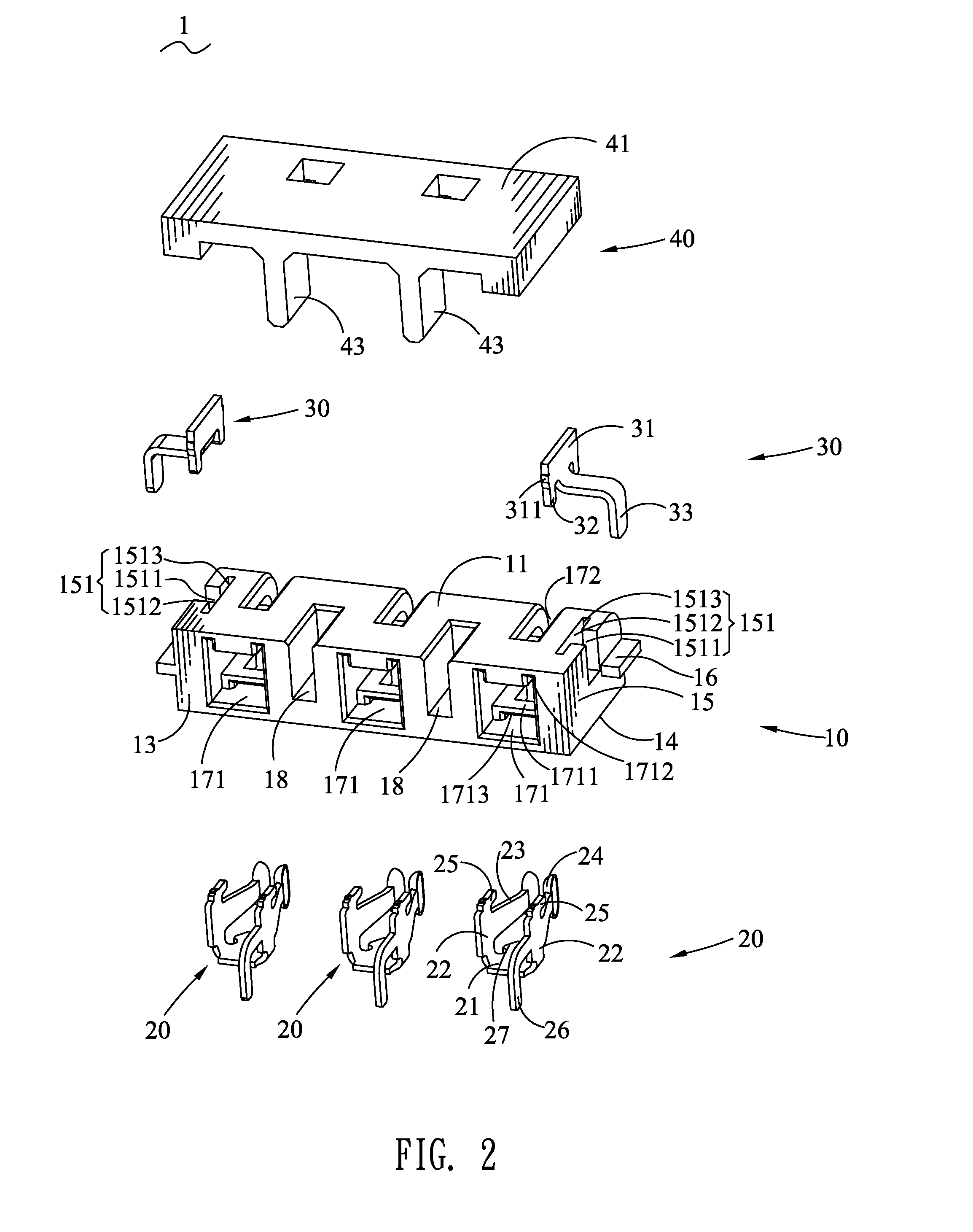
[0016]Referring to FIGS. 1-2, a battery connector 1 according to the present invention is shown. The battery connector 1 includes an insulating housing 10, a plurality of terminals 20, two holding elements 30 and a cover 40.

[0017]Referring to FIGS. 1-3, the insulating housing 10 is of a cuboid shape and has a top surface 11, a front surface 12, a rear surface 13 opposite to the front surface 12, a bottom surface 14 opposite to the top surface 11 and two opposite side surfaces 15. The top surface 11 and the front surface 12 are connected with each other by an arc face 101. Substantial middles of the two opposite side surfaces 15 oppositely protrude to form two locating pieces 16 extending longitudinally and adjacent to the front surface 12 and the rear surface 13, respectively. Two opposite ends of the insulating housing 10 respectively define a fixing slot 1512 extending longitudinally and penetrating through the top surface 11, and a receiving channel 1511 connected with a middle o...


PUM


Abstract

A battery connector is adapted for being assembled to a printed circuit board. The battery connector includes an insulating housing, two holding elements and a plurality of terminals. The insulating housing has two opposite side surfaces. The insulating housing defines a plurality of terminal cavities and receiving grooves. Two holding grooves are opened in two opposite ends of the insulating housing. Each side surface of the insulating housing protrudes sideward to form a locating piece. Each holding element has a base plate mounted to the holding groove and a holding piece projecting out of the holding groove to be inserted into the printed circuit board. The terminals are respectively received in the terminal cavities. Each terminal has two contacting portions having an interstice therebetween and facing towards the receiving groove, and a soldering portion projecting out of the terminal cavity to be inserted in the printed circuit board.

Description

BACKGROUND OF THE INVENTION[0001]1. Field of the Invention[0002]The present invention generally relates to a battery connector, and more particularly to a battery connector capable of being located on a printed circuit board firmly and accurately.[0003]2. The Related Art[0004]With the fast development of the information industry, portable electronic apparatuses have been widely used in our daily life, such as video cameras, personal digital assistants (PDA) and mobile phones and so on. Electrical connectors used in the portable electronic apparatuses, especially battery connectors have played an irreplaceable role on the various communication apparatuses.[0005]In general, the battery connector includes an insulating housing and a plurality of terminals. Each of the terminals has a contacting portion and a soldering portion. The terminal is mounted in the insulating housing with the contacting portion being exposed outside to connect with one battery so as to provide power for the el...

Claims


Application Information

Patent Timeline
Patent Type & Authority Patents(United States)
IPC IPC(8): H01R12/00
CPCH01R12/7052H01R12/707H01R12/724
Inventor YANG, CHIH-LINWANG, CHIN-CHOU
Owner CHENG UEI PRECISION IND CO LTD
Why Eureka
Try Eureka