U-shaped steel and anchor cable collaborated support structure for laneway with large-deformation deep part

A support structure and large deformation technology, applied in tunnels, tunnel linings, shaft linings, etc.

Inactive Publication Date: 2014-07-30
HUNAN UNIV OF SCI & TECH
View PDF7 Cites 15 Cited by
  • Summary
  • Abstract
  • Description
  • Claims
  • Application Information

AI Technical Summary

Problems solved by technology

Traditional support methods, such as anchor rods, anchor cables, U-shaped steel and their combination support methods, either have insufficient support strength, or are not suitable for the deformation of the surrounding rock, resulting in insufficient compressive performance, and most of them end in failure.

Method used


Image

  • U-shaped steel and anchor cable collaborated support structure for laneway with large-deformation deep part
  • U-shaped steel and anchor cable collaborated support structure for laneway with large-deformation deep part
  • U-shaped steel and anchor cable collaborated support structure for laneway with large-deformation deep part

Examples


Embodiment Construction

[0016] The present invention will be further described below in conjunction with the accompanying drawings and embodiments.

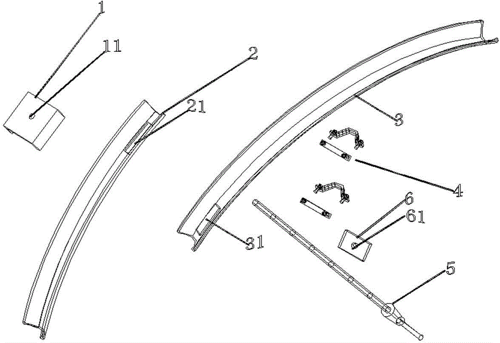
[0017] Such as figure 1 As shown, the present invention includes a channel steel block 1 , a first U-shaped steel segment 2 , a second U-shaped steel segment 3 , a card cable 4 , an anchor cable 5 , and a backing plate 6 . The corresponding positions on the first U-shaped steel section 2 and the second U-shaped steel section 3 are provided with rectangular holes 21, 31 for the passage of the anchor cable 5, and the first U-shaped steel section 1 and the second U-shaped steel section 1 and the second U-shaped steel section are connected by the clamp cable 6. The section 2 is fixed firmly, the channel steel block 1 is placed behind the rectangular hole, and the backing plate 6 is located at the contact position between the U-shaped steel and the anchor cable 5 lockset.

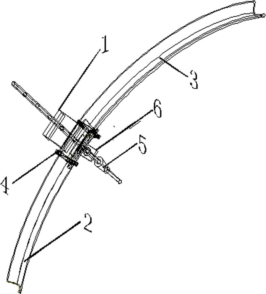
[0018] Such as image 3 As shown, the middle part of the channel steel block 1 and...


PUM


Abstract

The invention discloses a U-shaped steel and anchor cable collaborated support structure for a laneway with a large-deformation deep part. The U-shaped steel and anchor cable collaborated support structure comprises a first U-shaped steel section, a second U-shaped steel section, an anchor cable, clamp cables, a channel steel block and a cushion plate; one end of the first U-shaped steel section and two ends of the second U-shaped steel section are provided with rectangular holes with the same standard; round holes with the diameter equal to the diameter of the anchor cable are formed in the middles of the channel steel block and the cushion plate; the first U-shaped steel section and the second U-shaped steel section are overlapped; the rectangular hole in one end of the first U-shaped steel section and the rectangular hole in one end of the second U-shaped steel section are overlapped; the first U-shaped steel section and the second U-shaped steel section are fixed by the clamp cables; the opening of the channel steel block is reversely buckled in the opening at the overlapping position of the first U-shaped steel section and the second U-shaped steel section; the anchor cable penetrates through the channel steel block, the first U-shaped steel section, the second U-shaped steel section and the cushion plate to be fixed. The U-shaped steel and anchor cable collaborated support structure for the laneway with the large-deformation deep part is simple in structure, convenient to use and long in service life, the support strength is improved and integral damage is not easily generated.

Description

technical field [0001] The invention belongs to the field of engineering construction and application, and in particular relates to a coordinated support structure of U-shaped steel and anchor cables used in large deformation roadways in deep mines. Background technique [0002] U-shaped steel bracket refers to a plurality of U-shaped steel sections connected to each other through metal connectors to form a semi-(full) closed metal bracket that matches the cross-sectional shape of the roadway. It is widely used because of its simple structure, good performance, convenience and practicality, and moderate price. [0003] At present, in the support construction of shafts and geotechnical engineering, U-shaped steel metal connection devices are used to fix and connect two U-shaped steel sections that have been superimposed and overlapped at the end. This support method has a strong role in shaft engineering. adaptability. However, with the continuous increase of the mining dep...

Claims


Application Information

Patent Timeline
Patent Type & Authority Applications(China)
IPC IPC(8): E21D11/00
Inventor 王卫军郭罡业余伟健
Owner HUNAN UNIV OF SCI & TECH
Why Eureka
Try Eureka